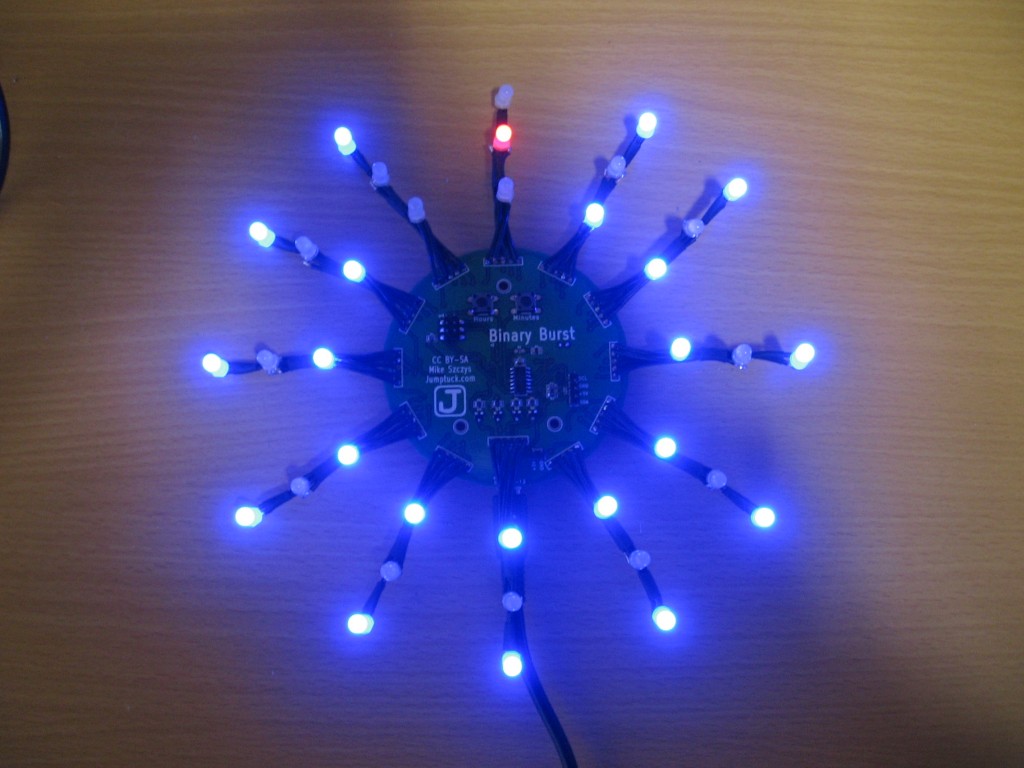
I finally got around to taking some pictures and shooting some video of my assembled clock project. Above you can see it displaying time. Minutes are tracked by the blue LEDs in binary code. Each spire has three digits, when the inner and outer digits are lit it shows a binary five and the next spire starts counting. Hours are displayed as a red LED corresponding to the positions on an analog clock. Here it is 12:54.
After the break you can see the video of the clock in action, as well as a description of what went into the build. You’ll also find some close-up pictures and a bit more info.
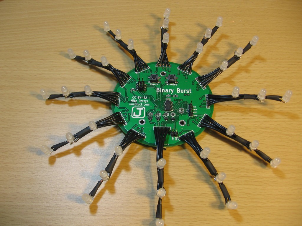
The assembled hardware
This is pretty good look at the assembled clock. If you didn’t see my last post, I made a fast-motion video when soldering the board. I intended to do the same thing with the spires but unfortunately I somehow lost the video I made.
Testing the board before soldering LEDs
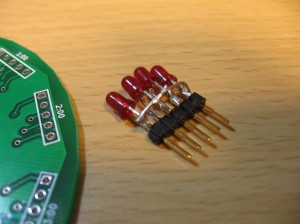 One thing I made sure to do before I started soldering the LEDs was to test the board. I programmed the ATtiny44 (actually, I think I’m using an ATtiny84 but they’re pin compatible) and then used this little module that I made to test all of the connections.
Since each spire connects to a 1×5 grid of 0.1″ pitch holes a pin header worked perfectly for testing. I just soldered four small LEDs in the same electrical orientation as the multiplex on the PCB. The test code I used lights each LED in sequence, pausing 300 milliseconds before moving to the next.
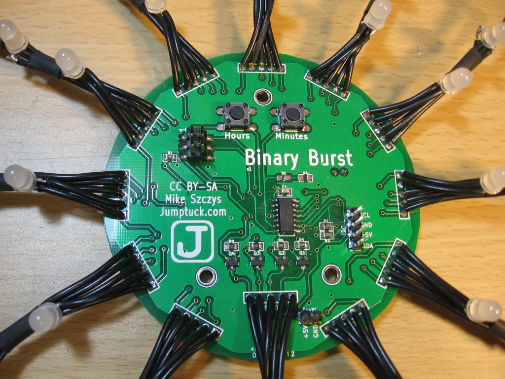
The components:
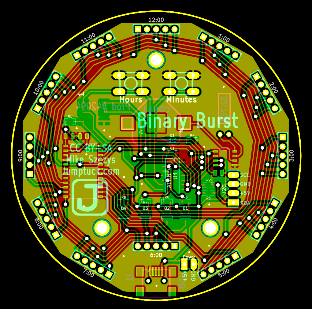
On the front of the board I have two tactile switches at the top. These will be used primarily for setting hours and minutes, but I plan to use long-press, and pressing both at once to add functionality. I think there is room for a couple of different display techniques (mimicking analog clock hands, etc.). I also want to add control for the intensity of the LEDs. These look just fine during the day, but at night they seem way too bright.
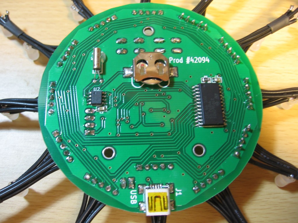
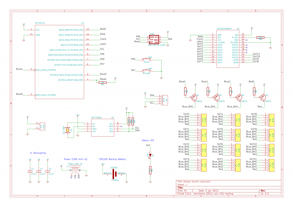
To the left there’s a 2×3 pin header for ISP programming. At the center of the board is the ATtiny44/84 that drives the clock, and to the bottom right there’s an I2C pin header and power header. Also on this side are the four PNP transistors that are used for multiplexing, and an ill-advised status LED pad. This LED has not been populated because it shares a pin with the minutes button. The two cannot be used at the same time without damaging the microcontroller.
The back side of the board hosts the RTC hardware, sink driver, and USB connector. The USB is only for 5V regulated power, and provides no data connectivity. The sink driver (STP16CP05) is my new favorite part. It’s a constant current driver so you just set one resistor value and it takes care of the rest. This greatly simplifies the multiplexing since I’m using two different color LEDs that have different voltage drops.
The RTC hardware includes the chip itself (MCP7940) and uses a CR1220 backup battery and a 32.768 kHz clock crystal to keep time. It seems to be running a little fast but there’s a calibration register which I’ll look into as I work more on the code. So far I’ve done all of the writing to the RTC, and the debugging using a Bus Pirate.
PCB, parts, and code
I developed the board using Kicad. This was my first Kicad project and I have to say I like it a lot more than Eagle, with which I’m already well versed. I ordered the PCBs from Seeed Studios. It was a great experience and I’m sure I’ll use the service again in the future.
All of the board information, as well as source code is available from my Github repository.
Update: Bill of Materials with Mouser parts numbers.
Next project:
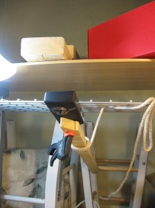
I think my next project should probably be to build some type of camera tripod. I’ve shot the last couple of videos at the bench using the setup seen here. It’s a chunk of scrap wood tied to some stools and the shelf above my soldering station. I use a quick clamp to mount the Flip camera in place. It works, but it’s not very adjustable.


