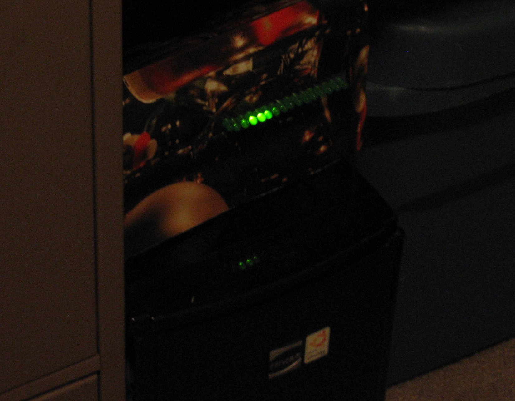
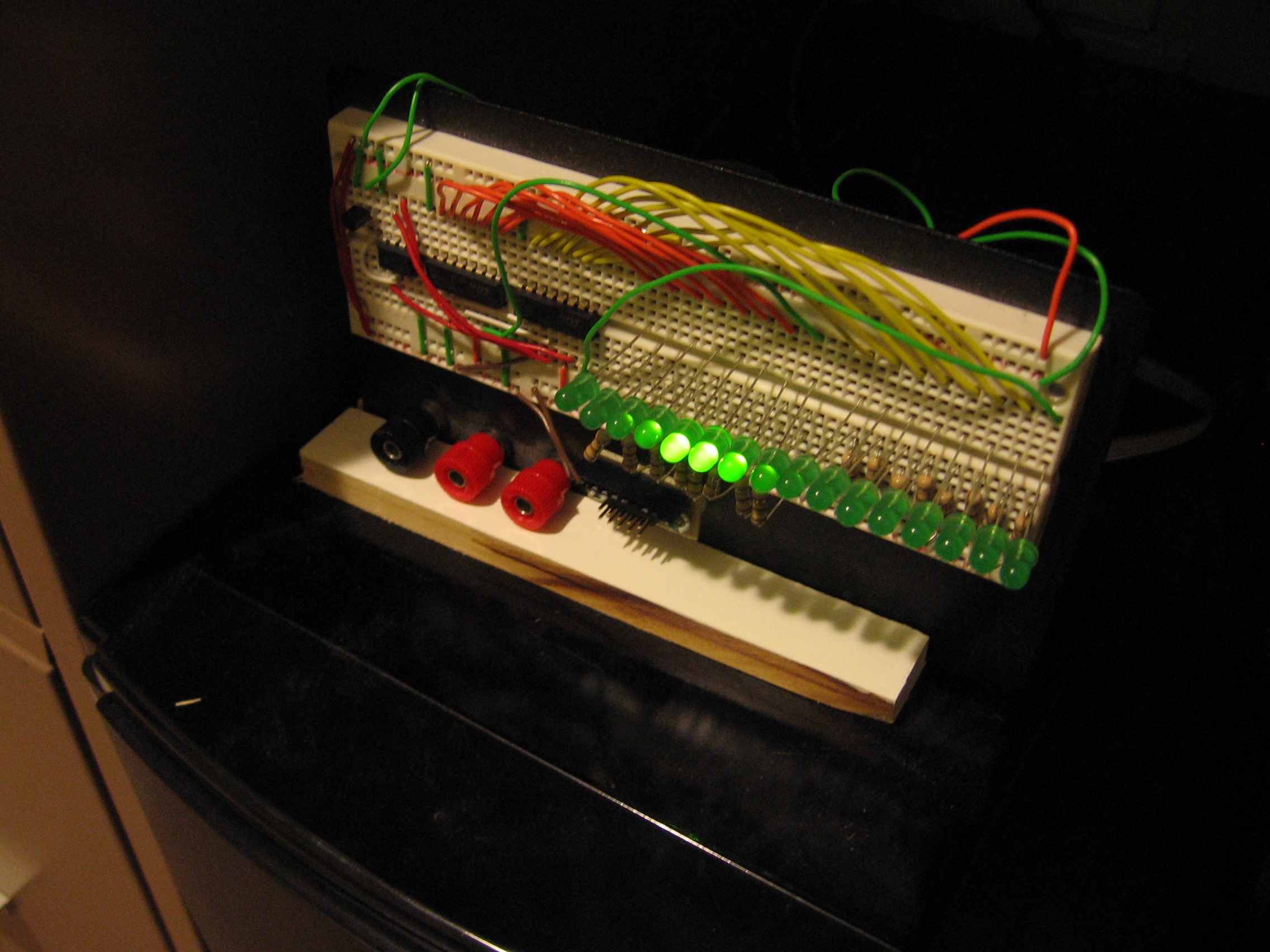
I decided to finish up my Cylon Eye (Larson Scanner) project by adding it as a status indicator for my computer. I record over the air programming and transcode it to DVD quality. Since things can be a bit slower when FFmpeg is running, I set it up for the Eye to scan to let me know it’s processing a video file in the background. All the details after the break but here’s the gist of the system:
- Python script started by the FFmpeg transcoding script
- It controls the Parallel port, driving pin 1 high to turn on the cylon eye
- the ‘pidof’ command is called every minute for FFmpeg. When it is not found, the cylon eye is turned off and the script exits
Starting and stopping with FFmpeg
It was not too hard to set up triggers when FFmpeg starts and stops transcoding. Those who have read about my MythTV setup will know I’m using a script to do the transcoding. I simply added a line to that script which launches my notifier script.
The notifier grabs control of the parallel port, driving data pin 1 high. This turns on the Cylon Eye (which I’ll cover in just a moment–that’s it in the picture). The script continues to run, checking for the FFmpeg PID every minute. When it no longer finds it, the Eye is turned off and the script exits.
import os
import parallel
import time

#Instantiate the parallel port as an object
parPort = parallel.Parallel()

#Set the output values of that object
parPort.setData(0x01)

def ffmpeg_running():
	test = ''
	p = os.popen('pidof ffmpeg')

	while 1:
	    line = p.readline()
	    if not line: break
	    test += line

	if test:
	    return True
	else:
	    return False

while(1):
	time.sleep(60)	#Wait 1 minute before checking if ffmpeg is running
	if not ffmpeg_running():
		break

parPort.setData(0x00)	#Turn off Cylon Eye
parPort = None
Using the parallel port as I/O
 This is a desktop computer and not surprisingly it has a parallel port that I don’t use. This makes it super easy to connect external hardware to the computer. I just used a resistor to connect data pin 1 to the base of an NPN transistor. This transistor connects one pin of a microcontroller to ground when the base is driven high. On the microcontroller side of things it’s exactly the same as using a button for input.
When I first got into working with AVR chips I built a DAPA programmer. this is just a parallel port connector that provides ground, and four data pin connections. I already have resistors on those lines so it’s perfect for this application — especially because it’s just been sitting in a box for years.
Driving the port is really easy thanks to a Python module which does all the work.
The scanning hardware
This is the same Larson Scanner hardware concept I’ve been working on for a while. I’m now using Binary Coded Modulation instead of PWM to dim the LEDs. I also transitioned from a KITT (Knight Rider) effect over to a Cylon Eye (Battlestar Gallactica) effect. The KITT type chases one LED, the Cylon Eye has a faded leader as well as a faded tail.
I prototyped this using an ATmega168, driving shift registers using the hardware SPI. But I don’t really need that bulky chip. Here I’ve ported the code to an ATtiny13, bit-banging the shift registers. Here’s the branch of code I’m using.
There is also a dirty hack in the main loop that looks for the signal from the computer’s parallel port. If the parallel port isn’t pulling the uC pin low via that NPN transistor, a blocking function disables the global interrupts. There is a timer interrupt that is responsible for displaying data on the shift registers. With the interrupts disabled the LEDs will not scan. This blocking function also blanks the display, then loops until the Python script drives the parallel port low.
This is a lazy way to set up the interface. The chip is still running at 8 MHz the entire time the computer is on, even if it’s not transcoding anything. If this becomes a permanent fixture on my computer I’ll look into using the sleep mode of the microcontroller instead of just looping until the input goes low.
The results
Conclusion
I’ve had a lot of fun with this project. It’s been through several iterations and I’ve learned something at each point along the way.
I have some future improvements planned. I’d like to solder this together and put it either in the computer case, or in its own project box. But I don’t really want to bother with the point-to-point soldering. So this might become my first fabbed PCB if I get around to it.
Other than final assembly I’ve achieved every goal I set out for!


