When I was first starting out with Zephyr last year I tried to get Lilygo’s TTGO T-Display working with little success. Now, with twelve more months of Zephyr experience under my belt I picked it up again and got it working quite easily. Let’s take a look at the process.
Overview
The display uses an ST7789 controller, and Zephyr has a driver that works with just a few configuration tweaks. In tailoring for this particular screen I found a few tripping points that need to be addressed to get everything working:
- The backlight must be driven. I had the display working but didn’t realize it because you can’t see pixels without turning on the backlight. (This is so obvious after the fact!)
- An overlay file must define both the ST7789 node, and assign that node as the chosen display.
- Memory offsets need to be configured to position the image correctly on the display. When the offsets are wrong, you will see uninitialized memory (noise) on the edges of an otherwise correct image.
- The ordering of the colors for this display is BGR (not RGB).
Code for the application shown in the video is available on GitHub.
Creating the Devicetree overlay file
A good starting point is to look at the Zephyr Bindings Index entry for this display. There are an awful lot of parameters to set, but we’re lucky that a couple of shields already exist that use this driver. I’ve copied the st7789v_waveshare_240x240 overlay. Here is the full overlay file I created based on that example.
/ {
	aliases {
		led0 = &led0;
	};

	chosen {
		zephyr,display = &st7789v;
	};

	leds {
		compatible = "gpio-leds";
		led0: led_0 {
			gpios = <&gpio0 4 GPIO_ACTIVE_HIGH>;
			label = "Green LED 0";
		};
	};
};

&spi3 {
	st7789v: st7789v@0 {
		compatible = "sitronix,st7789v";
		spi-max-frequency = <20000000>;
		reg = <0>;
		cmd-data-gpios = <&gpio0 16 GPIO_ACTIVE_LOW>;
		reset-gpios = <&gpio0 23 GPIO_ACTIVE_LOW>;
		vcom = <0x28>;
		gctrl = <0x35>;
		vrhs = <0x10>;
		vdvs = <0x20>;

		/* Landscape */
		width = <240>;
		height = <135>;
		x-offset = <40>;
		y-offset = <52>;
		mdac = <0xA8>;

		gamma = <0x01>;
		colmod = <0x55>;
		lcm = <0x0C>;
		porch-param = [0C 0C 00 33 33];
		cmd2en-param = [5A 69 02 01];
		pwctrl1-param = [A4 A1];
		pvgam-param = [D0 00 02 07 0A 28 32 44 42 06 0E 12 14 17];
		nvgam-param = [D0 00 02 07 0A 28 31 54 47 0E 1C 17 1B 1E];
		ram-param = [00 E0];
		rgb-param = [CD 08 14];
	};
};

&pinctrl {
	spim3_default: spim3_default {
		group1 {
			pinmux = <SPIM3_SCLK_GPIO18>,
				 <SPIM3_CSEL_GPIO5>;
		};
		group2 {
			pinmux = <SPIM3_MOSI_GPIO19>;
			output-low;
		};
	};
};
Many of the values have been changed from the example. For the bulk of the
screen initialization settings, I copied over what is used in the TTGO
library.
There are a couple of commands missing in the Zephyr implementation (e.g.
ST7789_CASET, ST7789_RASET) but they are set to the defaults anyway. The
only suspicious command I found is 0xB6 which is a register that doesn’t
appear at all in the ST7789 datasheet but there is a 0xB6 command called in the
driver.
Display orientation and Color Ordering
By default the display is set up for portrait orientation using these parameters:
		/* Portrait */
		width = <125>;
		height = <240>;
		x-offset = <52>;
		y-offset = <40>;
		mdac = <0x08>;
I worked out the x and y offset values for this screen using trial and error. To
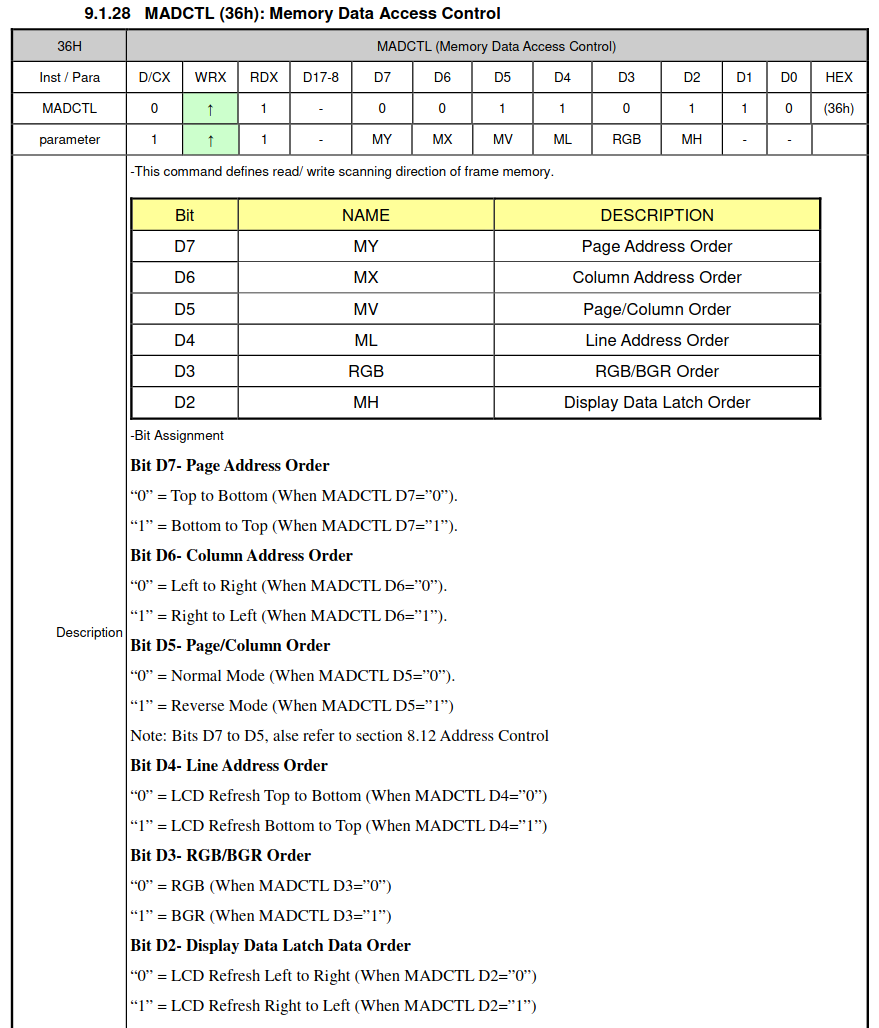
change orientation, the width/height and offset values are simply swapped. All
the real orientation magic happens in the Memory Data Access Control (MADCTL)
register, represented in the overlay by mdac.
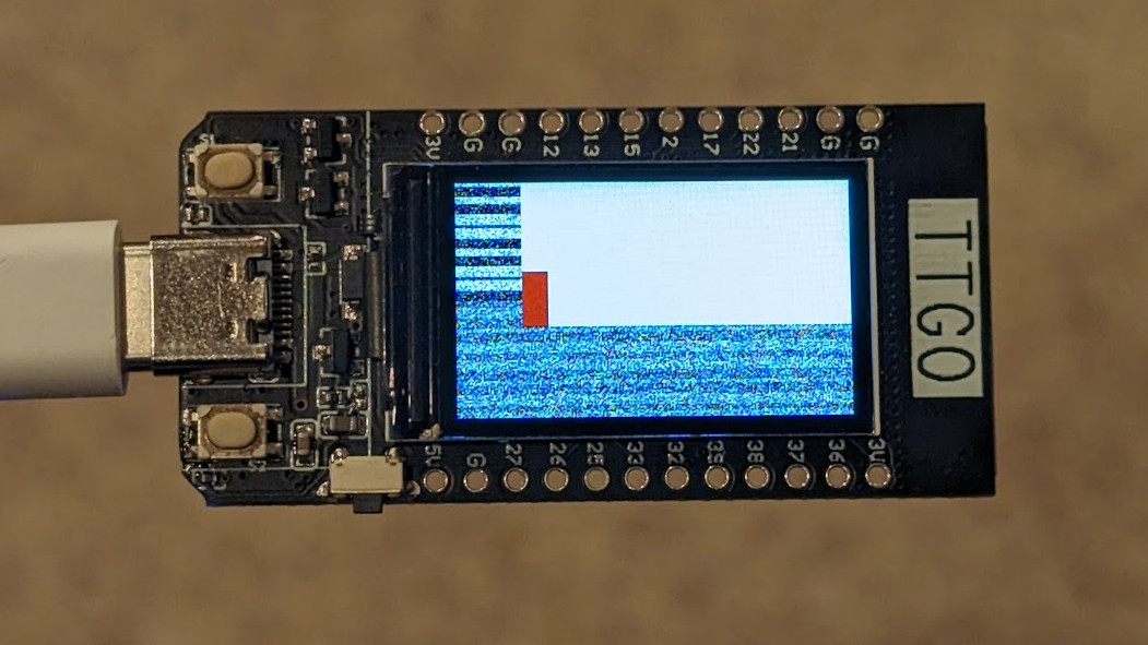 The offset values are needed to display the white rectangle within the confines
of the screen edges. In this image you can also see a red rectangle in one
corner. This should be blue but is displayed incorrectly because of the
configured color order.
The offset values are needed to display the white rectangle within the confines
of the screen edges. In this image you can also see a red rectangle in one
corner. This should be blue but is displayed incorrectly because of the
configured color order.
For this display, a 0x08 value is necessary to change the color order from RGB
to BGR. The 0xA or 0x0 values select between 90-degree rotation and 0-degree
rotation via memory manipulation. So the mdac for portrait is 0xA8 and for
landscape it’s 0x08.
Pin Control and Backlight Operation
The overlay file needs to configure the pins for the screen and backlight.
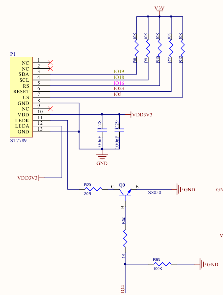
The ST7789 communicates over SPI so I have selected the ESP32’s SPI3 peripheral
and used pinctrl to remap the pins. Other than the RS connection, which maps
to the cmd-data-gpios, the labels are pretty straight-forward.
&pinctrl {
	spim3_default: spim3_default {
		group1 {
			pinmux = <SPIM3_SCLK_GPIO18>,
				 <SPIM3_CSEL_GPIO5>;
		};
		group2 {
			pinmux = <SPIM3_MOSI_GPIO19>;
			output-low;
		};
	};
};
I used the led0 alias because Zephyr’s display sample turns that standard LED
on at run time. This is a convenient way to turn the backlight on, but should
probably be mapped differently in your own project.
/ {
	aliases {
		led0 = &led0;
	};

	leds {
		compatible = "gpio-leds";
		led0: led_0 {
			gpios = <&gpio0 4 GPIO_ACTIVE_HIGH>;
			label = "Green LED 0";
		};
	};
};
Choosing the display
The best thing about Zephyr is its abstraction layers. With the ST7789 drive configured, all that’s needed to tie it into the RTOS is to associate the node as the chosen display. Here’s the bit from above that accomplishes that:
/ {
	chosen {
		zephyr,display = &st7789v;
	};
};
Building the Zephyr Display Sample
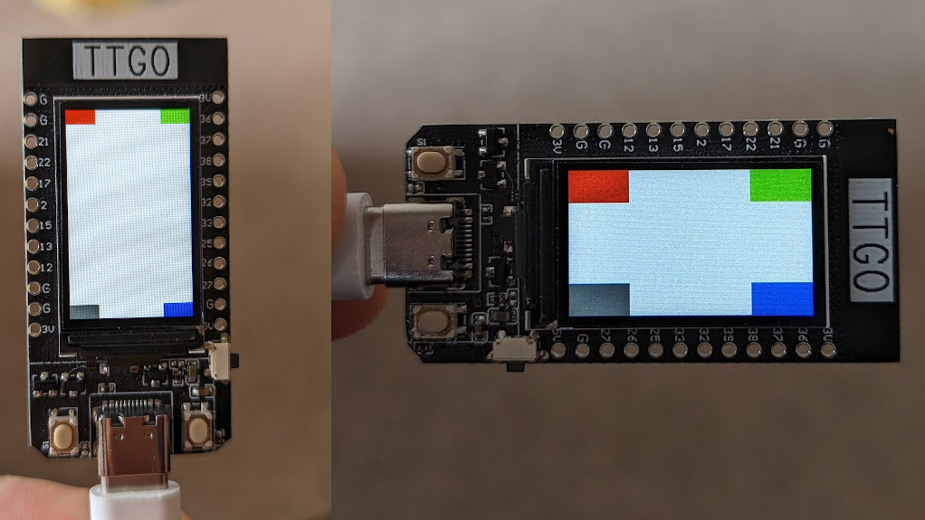 The Zephyr display sample shown in both portrait and landscape. If configured
correctly, the rectangles will be red, green, blue, and fading gray (clockwise
starting in the upper left).
The Zephyr display sample shown in both portrait and landscape. If configured
correctly, the rectangles will be red, green, blue, and fading gray (clockwise
starting in the upper left).
Now that we have an overlay file, the Zephyr Display Sample can be built for this board.
$ cd zephyr/samples/drivers/display
$ west build -b esp32 .
$ west flash
Bonus: Using LVGL
I was able to get get LVGL running on this display without much hassle, as shown in the video at the top of this post. The only thing I discovered is that color ordering is also an issue with the LVGL configuration. There is a Kconfig symbol that will swap the red and blue values to match what the display is expecting:
CONFIG_LV_COLOR_16_SWAP=y
Alas, I’ll have to leave the LVGL tutorial for another day ;-)