I haven’t put much time into the light-based programmer I was working on. But I did get some advice from Devlin Thyne who pushed me in a different direction on it. He suggested I use Manchester Encoding which only needs one input. It’s a method of rolling the clock signal and data into one. But before I do that, I’m going to switch over to using the AVR Analog Comparator hardware. It’s an easy way to get a 1 or 0 out of an analog input. See my simple example after the break.
The Analog Comparator section of the ATmega168 datasheet is pretty short. I was worried that it wasn’t well documented but it turns out you don’t need much help, it’s super easy to use.
Comparing two inputs
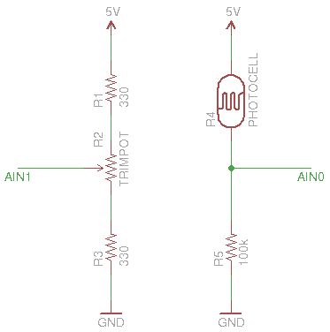
At its core, the comparator just samples two inputs, AIN0 and AIN1. If the voltage on AIN0 is high than AIN1 a digital 1 will be written to the ACO (the letter O, not the number 0) bit in the ACSR register. A digital 0 will be written if AIN0 is lower than AIN1.
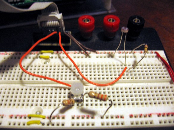
Basically, you want a reference voltage, and a variable voltage. I used a voltage divider to get 2.5V as my reference voltage. A second voltage divider with a photoresistor in it is the variable voltage.
Once you’ve hooked everything up getting the value in code is very simple. The analog comparator is already set to compare the two default inputs and if the interrupts are enabled it will trigger on both rising and falling edge (this is the toggle mode). In the code below, I enable that interrupt, then read the output of the comparator (ACO) to set or clear some LEDs on PORTB.


