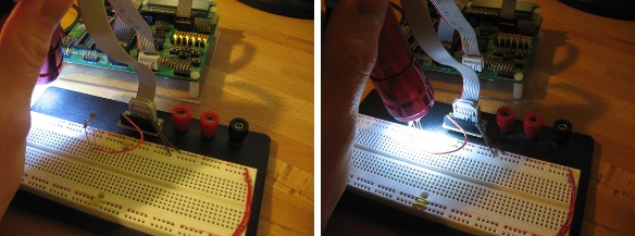
I’m starting on a new project and thought I’d share the first step. I eventually want to use two photoresistors to push data into the microcontroller. You’ve got to crawl before you can walk and I’ve set up a simple circuit to make sure everything is working.
Using a voltage divider that includes a CdS photoresistor I can take a measurement using the ADC that correlates to the intensity of light shining on that CdS sensor. In the video after the break I’m using a set of LEDs on the development board as a signal. When light intensity is low the LEDs are on. When I use a flashlight to increase the light intensity the LEDs go off.
This proves that I have everything set up correctly before I make my firmware more complicated. I followed along with the ADC tutorial over at AVR freaks to get this far. Eventually I’ll use two photoresistors, one to sense the clock and the other to sense the data. That will require interrupt based ADC readings. For now I’m using the free ranging mode. Keep reading to see the code.
#include

void initADC(void){
  ADCSRA |= (1<
  ADMUX |= (1<
  ADCSRA |= (1<
  ADMUX |= (1<
  ADCSRA |= (1<
  ADCSRA |= (1<
}

void initIO(void){
  DDRB = 0xFF;	//PortB as Outputs
  PORTB &= 0x00;	//All outputs low
}

int main(void){
  initIO();			//Initialize I/O
  initADC();		//Initialize ADC

  while(1){
    if (ADCH > 128) {
      PORTB = 0xFF;
    }
    else {
      PORTB = 0x00;
    }
  }
}


