A voltage divider uses two or more resistive elements to output a lower voltage than was input. This can have many functions, like allowing communications between devices operating at different voltages, and acting as inputs for devices that have variable resistance. After the break I’ll look at some of those uses, and cover the basic principles of voltage dividers.
Simple Voltage Divider
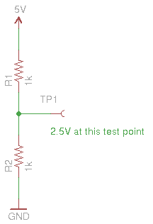
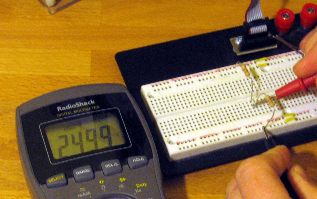
 Here is a schematic of the simplest voltage divider possible. You can see that there are two 1000 Ohm resistors in series between a 5V source and ground. The test point in between the two resistors is considered the output for the voltage divider. As labelled in the image, measuring voltage between the test point and ground will yield 2.5 Volts.
This circuit would be perfect if you were using a 2.5V microcontroller to monitor a digital logic pin on a 5V peripheral. The pin of the peripheral would be connected where the voltage source is in this schematic.
Calculating the output voltage from this circuit is pretty easy. Let’s take a look at the equation you need to use.
Doing the Math
$latex V_{out} = {\frac{Z_2}{(Z_1 + Z_2)}}*V_{in} &s=4$
Here is the basic equation governing voltage dividers. By reorganizing the equation you can calculate based on the target output value, or calculate the output based on the resistor values at hand. It is easy enough to plug in 1000 for all of the Z values (like the schematic above) and see that you end up multiplying the input value of 5 Volts by 1/2 to arrive at the output voltage of 2.5V.
This equation is a little less useful if you’re looking to use variable resistors, like a potentiometer, thermistor (varies with temperature), or photoresistor (varies with light intensity). These are all common applications because a well tuned voltage divider circuit will allow you to measure the output using the Analog to Digital converter of a microcontroller with great resolution and precision.
Variable Resistors in Voltage Divider Circuits
 Here is a circuit using a photoresistor as part of the divider. It can be placed on either side, the high side will cause the output voltage to increase as light intensity increases, and vice-versa if it is on the low side.
I struggled for quite some time looking to figure out an equation to find the best value for R2. In the end I found that Society of Robots has the best advice. They suggest measuring the high and low resistance values of the photoresistor, multiplying the values and using the square root of the result as your R2 value:
$latex R2=\sqrt[2](R1_{high}*R1_{low})&s=4$
I don’t know if this is the best possible equation. But I haven’t found a better way to calculate the resistors for this type of application yet. If you have, please let me know by leaving a comment.


