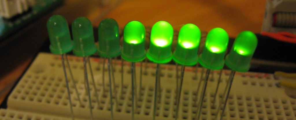
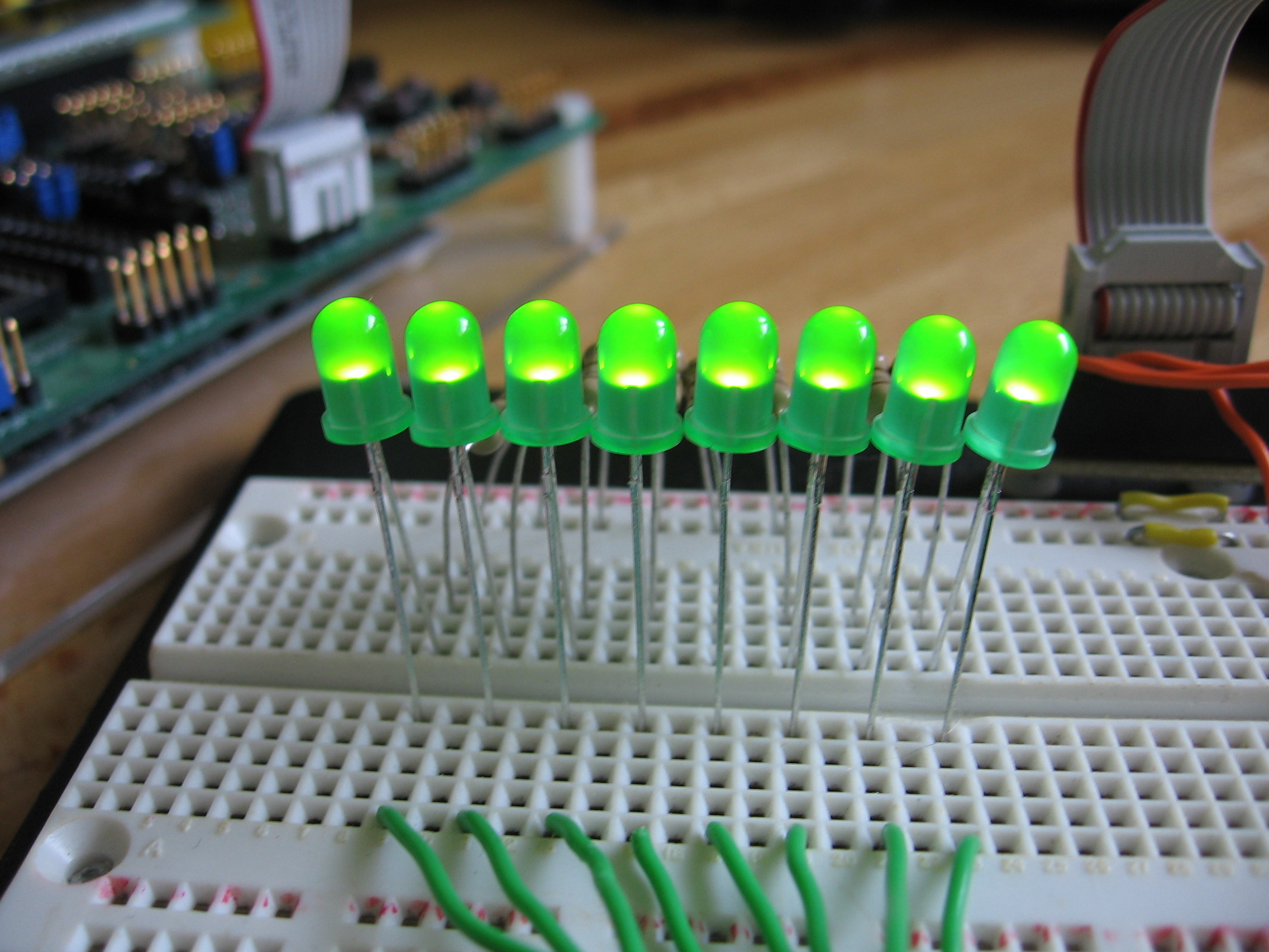
 I’ve been hard at working coding my own Larson Scanner. This is the iconic sweeping light seen in the Cylons on Battlestar Gallactica or on the front of KITT, the car from Knight Rider.
As I discussed in my previous post, the thing that makes these look neat is the fading tail that chases the brightest light. Originally that was accomplished with capacitors which caused the light to fade as they discharged. I implemented the same concept, using a microcontroller and pulse-width modulation to manage the fading.
After the break I’ll go through the development process and share the code. I did this using an AVR microcontroller but you can use any chip you want. The gist of my process is this:
- Develop software (interrupt) based pulse-width modulation
- Write a function to monitor PWM values and automatically subtract from those over time to cause automatic fading.
- Use a buffer to track which LED is ‘active’ and do not fade that one. As soon as that buffer is shifted the old ‘active’ diode will start to fade.
Simple, right? Here’s a video overview to convince you:
And of course you’ll want to look at the most recent code.
Update: There are a few improvements that can be made to this system. One is to use exponential values for different intensity levels for a smoother gradient. The other is to swap out Binary Coded Modulation (BCM) for PWM. Read more here.
Hardware:
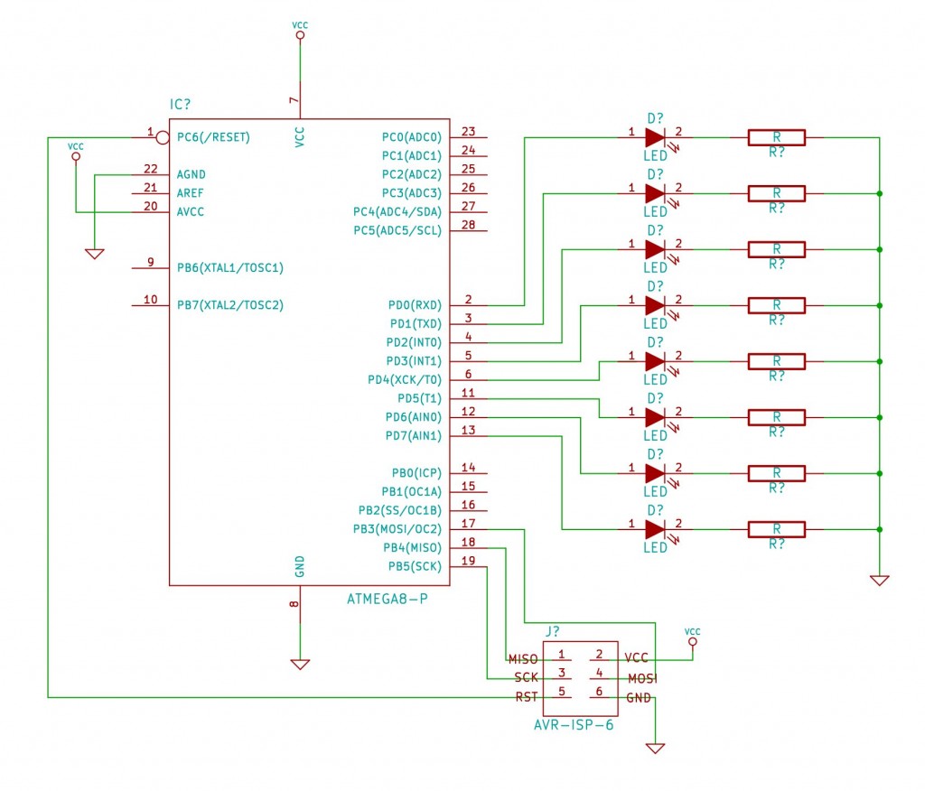
 It seems like I’m constantly building this same circuit on the breadboard. I do most of my prototyping with an ATmega168. Here I’ve connected eight LEDs, each with their own resistor, to the PORTD pins of the microcontroller. I’m using 180 Ohm resistors and I measure about 17mA of current running through each when powered at 5V.
I want to make sure you’ve hooked everything up correctly before starting with the software PWM. Here’s a github tag for that code but the import stuff is here:
#include <avr/io.h>
#include <avr/interrupt.h>

int main(void) {
  //Setup IO
  DDRD = 0xFF;
  PORTD = 0xFF;

  while(1){
    //Loop Forever
  }
}
It gives me a nice set of illuminated LEDs… and now I know the hardware is hooked up correctly.
Adding the PWM
Now let’s get down to work. In order to get the fading effect I need to use Pulse-Width Modulation. This is a fancy way of saying that we need to turn the LEDs on and off very fast. The percentage of on and off time account for different levels of brightness. I’m going to use an internal timer for this. Here’s how I plan to make it work:
- Timer overflows and Interrupt Service Routine starts
- All outputs are updated from buffer set during the last interrupt
- Software counter is incremented.
- Buffer is set for next interrupt by comparing the software counter to each LED’s PWM value. If the counter is higher than that value, the LED should be off, otherwise it should be on
The only real hard part about this is dealing with C syntax. Once again, here’s the github tag of the code at this point in development. I’ve added a couple of variables and an Interrupt Service Routine to the code.
volatile unsigned char pwmValues[8] = {0x00,0x20,0x40,0x60,0x80,0xA0,0xC0,0xE0,0xFF};
volatile unsigned char ledBuffer = 0x00;

ISR(TIMER0_OVF_vect)	//Timer0 overflow interrupt handler
{
  PORTD = ledBuffer;	//Set outputs prewound from last interrupt

  static unsigned char pwmCount = 255;	//Track overflows to compare with pwmValue
  if (++pwmCount == 0)
  {
    ledBuffer = 0x00;
    for (char i=0; i<8; i++)
    {
      if (pwmValues[i] != 0) ledBuffer |= (1<<i);
    }
  }
  else
  {
    for (char i=0; i<8; i++)
    {
      if (pwmCount > pwmValues[i]) ledBuffer &= ~(1<<i);
    }
  }
}
There are some important things to think about here:
- My variables need to be ‘volatile’ because they may be altered by both the ISR and the main program. That’s not happening yet, but it will later in development
- The ‘static’ keyword used in the ISR initializes the pwmCount variable the first time the program runs, but after that the value will be preserved for future use.
Can you match up the four jobs I needed to accomplish to the code written in the ISR? Good! But there’s two more things needed to get this code working. In the main function I need to start TIMER0 running with no prescaler and enable the overflow interrupt:
  //Setup Timer
  cli();		//disable all interrupts
  TCCR0B |= (1<<CS00);	//Start timer with no prescaler
  TIMSK0 |= (1<<TOIE0);	//Enable the overflow interrupt
  sei();		//enable all interrupts
I also need to burn the AVR fuses so that the system clock is not divided by 8. This will get it running at 8 MHz, which is fast enough to remove the flicker. For an ATmega168 I used this command:
avrdude -P usb -c dragon_isp -p m168 -U lfuse:w:0xE2:m
The last two arguments are the important ones, identifying the chip and burning the fuses. The first few identify by programmer and the port it is on. You’ll need to change that for your setup.
With the program running I get a gradient as expected with the PWM values I loaded into the array. Onwards and upwards, were really getting somewhere now!.
Automatic Fading
The next step in the process is to add a system that automatically changes the PWM values. I’ve written a function to do this for me which I call from the main function based on a timer flag set in the same interrupt taking care of the PWM.
Here’s some important things to remember about the counter and flag system I’m using. Since I’m using an INT as the counter I never want to change that variable outside of the ISR. This is because I would need to disable global interrupts to do so since an INT takes two write processes to change and if the interrupt fired in between those two changes I’d be in trouble. Instead, the ISR will watch for a match value with that counter and use a CHAR variable as a flag for the main function to avoid this issue.
Take a look at the code package at this point in development. I’ve declared my variables:
unsigned int fadeDelay = 624; // 1=32uSecs, 65535(max)=~2.1 secs
unsigned char fadeResolution = 8; //Fade steps (between 1 and 255)
unsigned int fadeCount = 0;
volatile unsigned char fadeFlag = 0;
Added code to the ISR to manage the count and set the flag:
  //Track time for fading effect
  if (++fadeCount > fadeDelay) {
    fadeFlag += 1;
    fadeCount = 0;
  }
Added code to the loop to watch for a flag and run the function:
    if (fadeFlag)	//Targer time has passed; time to do something
    {
      fade();
      fadeFlag = 0;
    }
And finally I wrote the fading function:
void fade(void)
{
  //Systematically reduces all non-zero pwmValues
  for (unsigned char i=0; i<8; i++) {
    if (pwmValues[i] > 0) {
      if (pwmValues[i] < fadeResolution) pwmValues[i] = 0;
      else pwmValues[i] -= fadeResolution;
    }
  }
}
There’s also a little bit of code in there for testing. It just checks to see if all of the LEDs are off and turns them back on again if so.
Adding Scanning for the win
The last piece of the puzzle is to do the scanning. Here’s what I need to happen:
- Light up one LED
- Wait a set length of time
- Turn that LED off and light up the one next to it
- Whenever we run out of LEDs (get to the end of the row) just switch directions
Take look at the github tagged code for this part of development. First the timing. I set up the same counter and flag system that I used with the fade function. Now the main loop looks for a scan flag and runs the larson_scanner() function when it get is. That function users a buffer to track with LED is on, and just shifts it to the left or the right depending on some variables:
void larson_scanner(void) {
  //Adjust scan direction if necessary
  if ((1<<0) & scanBuffer) scanDirection = 1;
  else if ((1<<7) & scanBuffer) scanDirection = 0;

  //Shift the scanBuffer
  if (scanDirection) scanBuffer <<= 1;
  else scanBuffer >>= 1;

  //Write new values to PWM buffer
  for (unsigned char i=0; i<8; i++) {
    if ((1<<i) & scanBuffer) pwmValues[i] = 0xFF;
  }
}
It was also necessary to modify the fade function. That’s because I don’t want to fade the LED that currently has the ‘focus’ of the scanning function. That turns out to be quite easy because the fade function can just check the buffer I’m using with the scanning function. Here’s the altered fade function:
void fade(void)
{
  //Systematically reduces all non-zero pwmValues
  for (unsigned char i=0; i<8; i++) {
    if (pwmValues[i] > 0) {
      if (~((1<<i) & scanBuffer)) { //Do not dim active LEDs from scanBuffer
        if (pwmValues[i] < fadeResolution) pwmValues[i] = 0;
        else pwmValues[i] -= fadeResolution;
      }
    }
  }
}
Fire it up and it works just like in the video. Here’s a direct link to the complete main.c file.
Conclusion:
Once you get elbow deep into this, it’s not hard to grasp the concepts. I’m happy with the outcome; it looks great and it’s fairly adjustable. I would like to look into a couple of different upgrades. It would be nice to make this work with cascading shift registers like 74HC595′s. That would really make expandability an option. I’d also like to give this a try with an Arduino, since I’m rather new to that hardware and I’m not entirely sure how their timing system would mesh with these concepts. Perhaps that’s for a future post.
Resources:
- Source code repository: https://github.com/szczys/Larson-Scanner/


