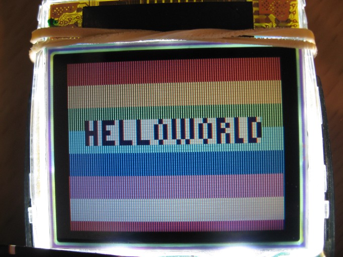
I have made quite a bit of progress. Here you see my “Hello World” on the nokia 3595 lcd screen. I have been pouring over the datasheet as well as examining code from two different projects to get to this point. It seems that I am having no problems addressing the display and writing to it. I do still have some work to do with the initialization sequence.
I’m out of space
The 2k of programming memory for the ATtiny2313 has been restrictive. The code I am currently running is 2000 bytes once compiled. I’m not sure I can do much more work without moving to a chip with more space for the program code.
Indeterminate Values
In the datasheet for the LCD controller there are several aspects that are indeterminate (not defined on the controller’s registers) at startup. I have set some of these such as the color lookup table for 8-bit color, but not others. I did try to set a few of these values but in each case I made the LCD non-responsive in doing so. In future work with this LCD I will attempt to find the correct values for these settings.
Indeterminate values I have set:
- Color Set
- Display Control
Indeterminate values I have not set:
- Gray scale position set 0
- Gray scale position set 1
- Temperature gradient set
- Refresh set
- Voltage control
- Common driver output select
- Power control
Addressing the Memory
Once I was able to get a response from the display (get it to turn on) I had some trouble addressing it. I was trying to address a single pixel location (ie: go to pixel x=24 y=16). I spent quite some time head scratching before I discovered in the datasheet that this display is addressed differently.
In order to write to the LCD’s display ram you need to specify the area you want to write to. This mean you send the command to address the columns then you send two bytes, the starting and ending values for the x axis. This is then repeated for the pages (rows) and finally the pixels are written.
Writing to the entire display (98×67 pixels) in 8-bit color mode:
- Send the command to address the columns (0x2A)
- Send the column location to start writing (0)
- Send the column to stop writing (97)
- Send the command to address the pages(rows) (0x2B)
- Send the row location to start writing (0)
- Send the row location to stop writing (66)
- Send the command to write to memory (0x2C)
- Send one byte for each pixel in the previously defined area. The byte represents the color you want the current pixel to be (RRRGGGBB). For this example we need to send 6566 bytes (98*67) in order to fill the area we have addressed.
Proof of Concept
You can see the LCD in action in the video below. The screen will turn on all pixels (white), turn off all pixels (black), display an XOR pattern, display horizontal color bars, and finally print HelloWorld. Source code is available at the bottom of the page.
#define F_CPU 8000000UL

#include <avr/io.h>
#include <util/delay.h>

#define LCD_PORT PORTB
#define LCD_DDR  DDRB
#define LCD_CLK (1<<PB0)
#define LCD_SIO (1<<PB1)
#define LCD_CS  (1<<PB2)
#define LCD_RST (1<<PB3)

/**Device Information**
* ATtiny2313          *
* lfuse=0xD4          *
* hfuse=0xDF          *
* efuse=0xFF          *
* Power=3.3v          *
**********************/

/**LCD Pinout*****************
* 1=Reset------>3.3v+        *
* 2=CS--------->Logic        *
* 3=GND-------->GND          *
* 4=SIO-------->Logic        *
* 5=SCL-------->Logic        *
* 6=VDigital--->3.3v+        *
* 7=VBoost----->3.3v+        *
* 8=VLCD--->0.22uf Cap-->GND *
*  (This cap may not be      *
*   optimal, other schematics*
*   have suggested 1uf)      *
*****************************/

//LCD_Out function comes from source code found here:
//http://hobbyelektronik.org/Elo/AVR/3510i/index.htm
//Unfortunately this is the only way I know to attribute
//this code to the writer.
void LCD_Out(unsigned char Data, unsigned char isCmd) {
    if(isCmd) LCD_PORT |= LCD_CS;
    LCD_PORT &= ~(LCD_CLK|LCD_CS);  //Clock and CS low

    LCD_PORT |= LCD_SIO;        //SData High
    if(isCmd) LCD_PORT &= ~LCD_SIO; //If it is a command, SData Low

    LCD_PORT |= LCD_CLK;        //Clock High

    for(char x=0; x<8; x++)    {
        LCD_PORT &= ~(LCD_SIO|LCD_CLK);        //Clock and SData low
        if(Data & 128) LCD_PORT |= LCD_SIO;      // Mask MSB - SData high if it is a 1
        LCD_PORT |= LCD_CLK;            //Clock High
        Data=Data<<1;                //Shift bits 1 left (new MSB to be read)
    }
}

void LCD_init(void)
{
  LCD_DDR |= (LCD_CLK | LCD_SIO | LCD_CS | LCD_RST);

  //Hardware Reset
  LCD_PORT &= ~LCD_RST;
  LCD_PORT |= LCD_RST;
  _delay_ms(5);

  LCD_PORT |= (LCD_CLK | LCD_SIO | LCD_CS);

  //Software Reset
  LCD_Out(0x01, 1);
  _delay_ms(10);

/*
  //Refresh set
  LCD_Out(0xB9, 1);
  LCD_Out(0x00, 0);
*/

  //Display Control
  LCD_Out(0xB6, 0);
  LCD_Out(128, 0);
  LCD_Out(128, 0);
  LCD_Out(129, 0);
  LCD_Out(84, 0);
  LCD_Out(69, 0);
  LCD_Out(82, 0);
  LCD_Out(67, 0);

/*
  //Temperature gradient set
  LCD_Out(0xB7, 1);
  for(char i=0; i<14; i++)  LCD_Out(0, 0);
*/

  //Booster Voltage On
  LCD_Out(0x03, 1);
  _delay_ms(50);  //NOTE: At least 40ms must pass between voltage on and display on.
          //Other operations may be carried out as long as the display is off
          //for this length of time.

/*
  //Test Mode
  LCD_Out(0x04, 1);
*/

/*
  // Power Control
  LCD_Out(0xBE, 1);
  LCD_Out(4, 0);
*/

  //Sleep Out
  LCD_Out(0x11, 1);

  //Display mode Normal
  LCD_Out(0x13, 1);

  //Display On
  LCD_Out(0x29, 1);

  //Set Color Lookup Table
  LCD_Out(0x2D, 1);        //Red and Green (3 bits each)
  char x, y;
  for(y = 0; y < 2; y++) {
      for(x = 0; x <= 14; x+=2) {
          LCD_Out(x, 0);
      }
  }
  //Set Color Lookup Table    //Blue (2 bits)
  LCD_Out(0, 0);
  LCD_Out(4, 0);
  LCD_Out(9, 0);
  LCD_Out(14, 0);

  //Set Pixel format to 8-bit color codes
  LCD_Out(0x3A, 1);
  LCD_Out(0b00000010, 0);

//***************************************
//Initialization sequence from datasheet:

//Power to chip
//RES pin=low
//RES pin=high -- 5ms pause
//Software Reset
//5ms Pause
//INIESC
  //<Display Setup 1>
    //REFSET
    //Display Control
    //Gray Scale position set
    //Gamma Curve Set
    //Common Driver Output Select
  //<Power Supply Setup>
    //Power Control
    //Sleep Out
    //Voltage Control
    //Write Contrast
    //Temperature Gradient
    //Boost Voltage On
  //<Display Setup 2>
    //Inversion On
    //Partial Area
    //Vertical Scroll Definition
    //Vertical Scroll Start Address
  //<Display Setup 3>
    //Interface Pixel Format
    //Colour Set
    //Memory access control
    //Page Address Set
    //Column Address Set
    //Memory Write
  //Display On

//****************************************

}

void Flash_BW(unsigned int flash_delay_ms)
{
  LCD_Out(0x13, 1);
  //All pixel ON
  LCD_Out(0x23, 1);
  _delay_ms(flash_delay_ms);

  LCD_Out(0x13, 1);
  //All pixel OFF
  LCD_Out(0x22, 1);
  _delay_ms(flash_delay_ms);

  LCD_Out(0x13, 1);
}

void XorScreen(void)
{
  //Screen is 96x65

  LCD_Out(0x2A, 1); //Set Column location
  LCD_Out(0, 0);
  LCD_Out(97, 0);
  LCD_Out(0x2B, 1); //Set Row location
  LCD_Out(0, 0);
  LCD_Out(66, 0);
  LCD_Out(0x2C, 1); //Write Data
  //Row 0-64
  for (char i=0; i<=66; i++)
  {
    //Column 0-95
    for(char j=0; j<=97; j++)
    {
      LCD_Out(j^i, 0);
    }
  }
}

void StripedScreen(void)
{
  unsigned char color_palate[] = {
    //BBGGGRRR
    0b00000111,    //Red
    0b00111111,    //Yellow
    0b00111100,    //Green
    0b11111000,    //Cyan
    0b11000000,    //Blue
    0b11000111,    //Magenta
    0b11111111,    //White
    0b00000111    //This should be 0x00(black) but for screen wrapping it was changed to Red
  };

  LCD_Out(0x13, 1);
  for (char i=0; i<8; i++)
  {
    LCD_Out(0x2A, 1);
    LCD_Out(0, 0);
    LCD_Out(97, 0);
    LCD_Out(0x2B, 1);
    LCD_Out(i*9, 0);
    LCD_Out((i*9)+8, 0);
    LCD_Out(0x2C, 1);
    for (int j=0; j<882; j++)
    {
      LCD_Out(color_palate[i], 0);
    }
  }
}

void Hello_World(void)
{
  //Binary representation of "Hello World"
  unsigned char Hello_World[5][5] = {
    0b10101110, 0b10001000, 0b01001010, 0b10010011, 0b00100110,
    0b10101000, 0b10001000, 0b10101010, 0b10101010, 0b10100101,
    0b11101100, 0b10001000, 0b10101010, 0b10101011, 0b00100101,
    0b10101000, 0b10001000, 0b10101010, 0b10101010, 0b10100101,
    0b10101110, 0b11101110, 0b01000101, 0b00010010, 0b10110110
  };

    LCD_Out(0x2A, 1);
    LCD_Out(8, 0);
    LCD_Out(87, 0);
    LCD_Out(0x2B, 1);
    LCD_Out(23, 0);
    LCD_Out(32, 0);
    LCD_Out(0x2C, 1);
    for (unsigned char i=0; i<5; i++) //Scan Rows
    {
      char h=2;
      while(h)
      {
    for (unsigned char k=0; k<5; k++) //Scan Columns
    {
      for (char j=0; j<8; j++)
      {
        if (Hello_World[i][k] & 1<<(7-j))    //Should there be a letter pixel here?
        {
          LCD_Out(0x00, 0);            //yes - draw it in black
          LCD_Out(0x00, 0);
        }
        else
        {
          LCD_Out(0xFF, 0);            //no - draw background in white
          LCD_Out(0xFF, 0);
        }
      }
    }
    --h;
      }
    }
}

int main(void)
{
  LCD_init();

  while(1)
  {
    Flash_BW(2000);    //Flash Black and White pausing for 2 seconds on each

    XorScreen();    //Fill screen with an XOR pattern, pause for 2 seconds
    _delay_ms(2000);

    StripedScreen();    //Fill Screen with colored stripes, pause for 2 seconds
    _delay_ms(2000);

    Hello_World();    //Write "Hello World", pause for 10 seconds
    _delay_ms(10000);
  }
}


