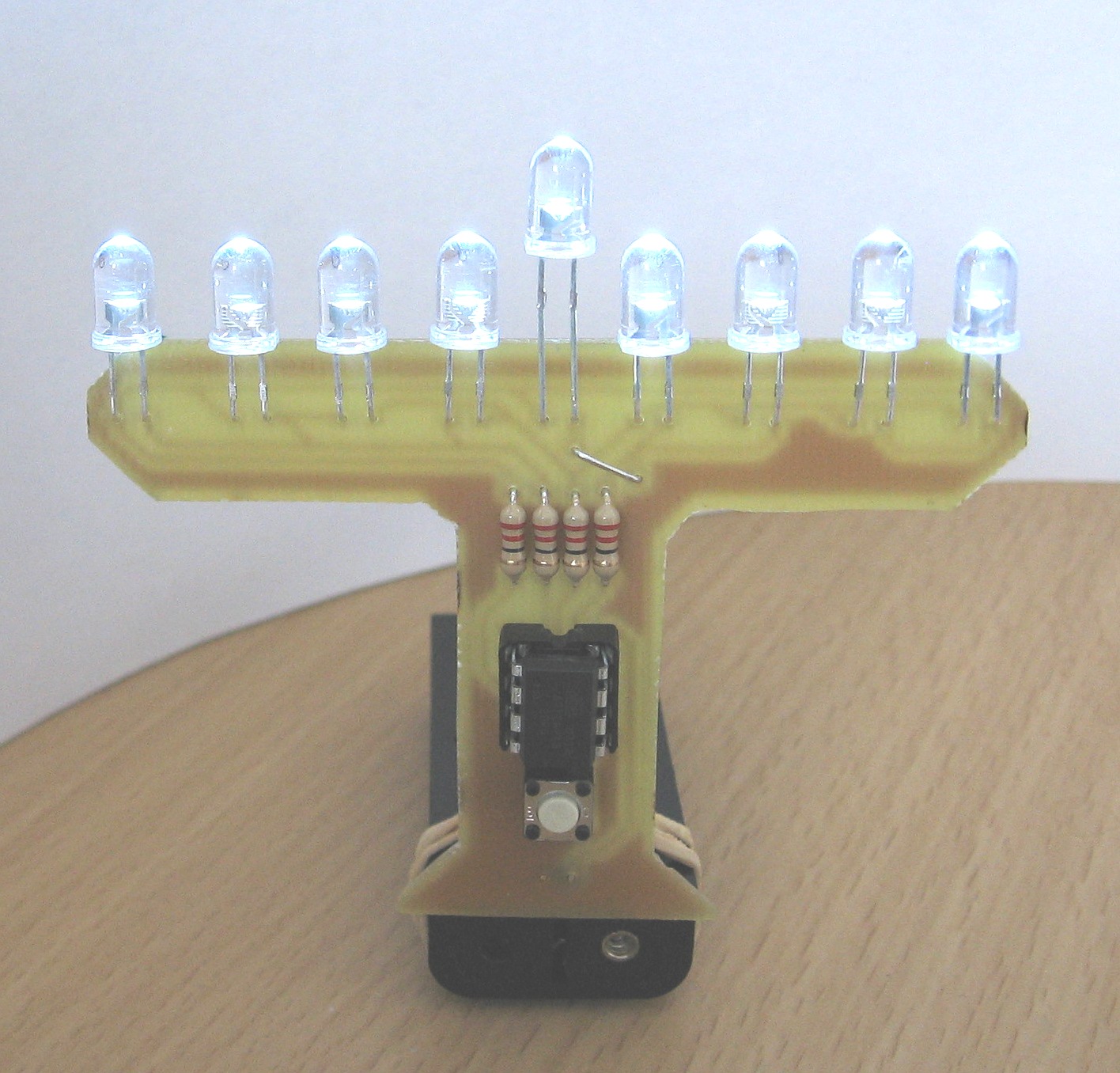
Last week on hack-a-day I saw their post on an LED Menorah that was powered by a 9v battery with the lights controlled by dip switches. I thought to myself, “gee, that’s not a very creative design”. There was redemption in the minimalist designs linked too showing a menorah soldered to a tiny2313 and one soldered to an LM2913, both without a circuit board.
These free formed designs were creative but a little too down and dirty for me. I thought I could do better, and immediately thought of the handful of tiny13 8-pin microprocessors I had sitting around. I wanted to make a menorah with the following features in mind:
- Controlled by an AVR ATtiny13
- Powered by ~3v (unregulated to save on parts)
- One button operation
- Sleep mode when the menorah “burns out” after an hour or so
I’m happy to say I did accomplish all of my goals. More after the break.
For more pictures check out my Instructable of this project: http://www.instructables.com/id/LED_Hanukkah_Menorah/
Parts List
- Power supply that puts out between 2.7v and 3.3v.
- 9 LEDs (I used white)
- 4 resistors (22ohm)
- 1 momentary push button
- 1 pin header (2 pins)
- 1 DIP socket (8 pins)
- 1 AVR ATtiny13 microcontroller
- 1 Circuit board of some type
PCB
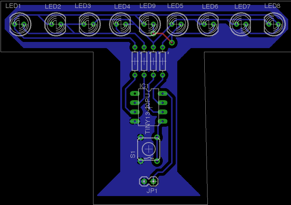
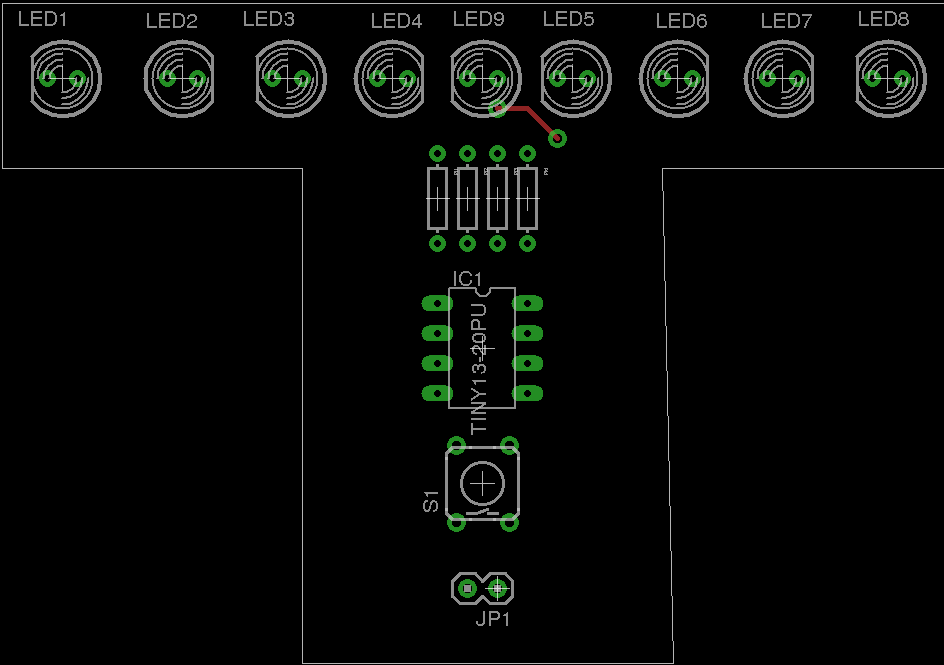
Here is the full board layout from Eagle CAD. You can see that I have managed just one place where I need to jump over a some traces (in red). I could have avoided this by running a track in between the two pads of LED9 but I avoided this to make etching the board easier.
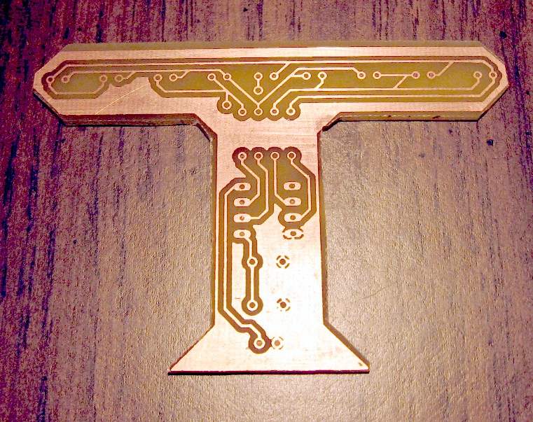
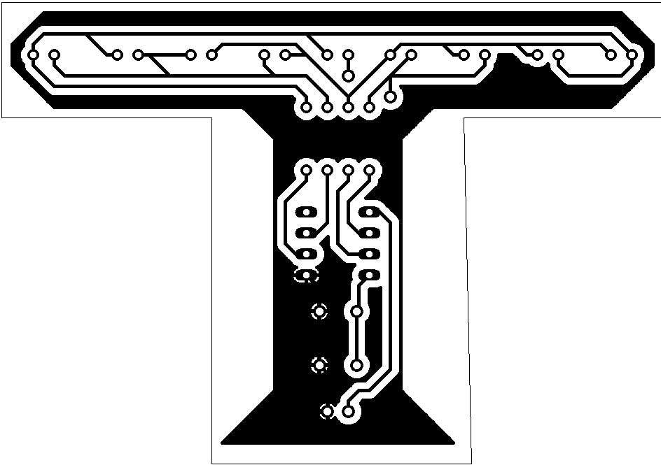
This is the PCB artwork. Click for a larger image, you should be able to print it and use it for your resist if you want to etch your own board. I use the toner-transfer method and find it is made easier if I surround my layout with a ground plane. This also decreases the amount of copper that the etchant needs to dissolve.
To help in assembly this image shows the component placement. Take great care in the polarity of the LEDs. As you can see, they are not all installed in the same orientation. Some are “flipped” to facilitate board layout.
Source Code
Here’s the source code for this project. I use avr-gcc to compile it and avrdude to program the uC. (Please note: there are clickable options at the top of the source code windows that will allow you to copy everything to clipboard and paste it into your favorite AVR development environment.
/**************************
* Application Information *
**************************/

/* Hardware Description:
Device: ATtiny13
Clock: Internal RC @ 1.2MHz (9.6Mhz with /8 prescaler)
hfuse: 0xFF
lfuse: 0x6A

LED Charlieplex on PORTB, PB1-PB4
Button on PINB, PB0

Power: 2 AAA batteries (3.3v-2.7v) unregulated
*/

/* Firmware Description:
This is an LED Haunnakah Menorah.  It has 9 leds,
4 or either side of a slightly higher shamash. When
powered up the shamash and the led farthest to the
right will light up.  They will "burn out" after approximately
one hour when the uC will go into sleep mode.  One
button press will wake the device up again and restart
the "burn out" timer.  A subsequent
button press will light the next led to the left.
*/

/*TODO:
-Measure power consumption/Estimate battery life
*/

#define F_CPU 1200000UL

#include <avr/io.h>
#include <avr/interrupt.h>
#include <util/delay.h>
#include <avr/sleep.h>

//These defines are used to help make this code portable
#define LED_DDR	DDRB
#define LED_PORT PORTB
//Charlieplexing (CP) bits:
#define CP0 	PB1
#define CP1 	PB2
#define CP2 	PB3
#define CP3 	PB4
#define LED_mask (1<<CP0 | 1<<CP1 | 1<<CP2 | 1<<CP3)
//Debounce definitions
#define KEY_DDR 	DDRB
#define KEY_PIN 	PINB
#define KEY_PORT 	PORTB
#define BTN1 		0
#define KEY_MSK 	1<<BTN1

/************
* Variables *
************/

//Charlieplexing index variables
char led_track = 0;			//Tracks what LED to address during interrupt
volatile unsigned char lights = 0;	//Tracks what LEDs should be illuminated

//Sleep timer variables
unsigned int ovf_cnt = 0;		//Counts interrupts up to 10 seconds
unsigned int ten_seconds = 0;           //Counts how many 10 second periods have passed
unsigned char sleep_flag = 0;

//Debouce variables
unsigned char debounce_cnt = 0;
volatile unsigned char key_press;
unsigned char key_state;

/***************************
* Initialization Functions *
***************************/

//Setup the timer to overflow without prescaler and enable overflow interrupt
void init_timers(void)
{
  cli();
  TCCR0B |= (1<<CS00);
  TIMSK0 |= (1<<TOIE0);
  sei();
}

void init_io(void)
{
  LED_PORT = 0x00;	//Set all outputs low
  LED_DDR |= LED_mask;  //Set LED pins as outputs
  KEY_DDR &= ~KEY_MSK; //Set Key pins as inputs
  KEY_PORT |= KEY_MSK; //Enable internal pull-up resistor for Key pins
}

//Setup pin change interrupt used to wake from sleep
void init_pcint(void)
{
  GIMSK |= 1<<PCIE;  //Enable Pin Change Interrupt
  PCMSK |= 1<<PCINT0; //Watch for Pin Change on Pin5 (PB0)
      //NOTE:This needs to change if button is connected to a different uC pin
}

/*********************
* Debounce Functions *
*********************/

unsigned char get_key_press(unsigned char key_mask)
{
  cli();               // read and clear atomic !
  key_mask &= key_press;                        // read key(s)
  key_press ^= key_mask;                        // clear key(s)
  sei();
  return key_mask;
}

/*****************
* Misc Functions *
*****************/

//Sleep function
void sleep_now(void)
{
  cli();
  lights = 0; //Turn all lights off
  TIMSK0 &= ~(1<<TOIE0); 	//Turn off the overflow interrupt
  LED_DDR &= ~(LED_mask);	//Set Charlieples pins as inputs
  LED_PORT &= ~(LED_mask);	//Set these pins low
  _delay_ms(500);
  init_pcint(); 		//setup pin change interrupt
  set_sleep_mode(SLEEP_MODE_PWR_DOWN);
  sei();
  sleep_mode();
  init_timers(); //Start execution again and exit
  _delay_ms(500); //Wait arbitrary amount of time so button doesn't get read upon resuming execution
}

/****************
* Main Function *
****************/

int main(void)
{
  _delay_ms(100); 	//Wait 100ms after startup before initialization (why?)
  init_io();		//Initialize input/output
  init_timers();	//Initialize timer

  while(1)
  {
    if (sleep_flag) //Auto-off timer reached, turn off device
    {
      sleep_flag = 0;
      sleep_now();
    }
    if( get_key_press( 1<<BTN1 ))
    {
      if(lights == 0) lights = 1<<7; //Turn first light on
      else if (lights == 0xFF) sleep_now();
      else lights = (lights>>1) | 1<<7; //Increment next light
    }
  }
}

/*************
* Interrupts *
*************/

//Timer0 Overflow Interrupt
ISR(TIM0_OVF_vect)
{
  //Sleep Mode Timer
  if (++ovf_cnt > 46875)
  {
    ovf_cnt = 0;
    if (++ten_seconds > 360)  //One minute has passed (change this to 1 hour later)
    {
      ten_seconds = 0;
      sleep_flag = 1;
    }
  }

  //This is the famous "danni debounce" code used with get_key_press function above.
  //It was written by Peter Dannegger: danni@specs.de
  if (++debounce_cnt > 46) //10ms has passed, run debounce code
  {
    static unsigned char ct0, ct1;
    unsigned char i;

    debounce_cnt = 0;

    i = key_state ^ ~KEY_PIN;    // key changed ?
    ct0 = ~( ct0 & i );          // reset or count ct0
    ct1 = ct0 ^ (ct1 & i);       // reset or count ct1
    i &= ct0 & ct1;              // count until roll over ?
    key_state ^= i;              // then toggle debounced state
    key_press |= key_state & i;  // 0->1: key press detect
  }
  //end of danni debounce code

  LED_PORT &= ~LED_mask; //All outputs toggled as ground
  LED_DDR &= ~LED_mask; //All pins as inputs
  if (++led_track > 8) led_track = 0; //Increment counter, fix if too high
  if (((1<<led_track) & lights) | (led_track == 8))	//Handle the charlieplex
  {
    switch (led_track)
    {
      case 0: LED_DDR |= (1<<CP2) | (1<<CP3);
              LED_PORT |= (1<<CP2);
              break;
      case 1: LED_DDR |= (1<<CP3) | (1<<CP2);
              LED_PORT |= (1<<CP3);
              break;
      case 2: LED_DDR |= (1<<CP0) | (1<<CP2);
              LED_PORT |= (1<<CP0);
              break;
      case 3: LED_DDR |= (1<<CP2) | (1<<CP0);
              LED_PORT |= (1<<CP2);
              break;
      case 4: LED_DDR |= (1<<CP1) | (1<<CP0);
              LED_PORT |= (1<<CP1);
              break;
      case 5: LED_DDR |= (1<<CP0) | (1<<CP1);
              LED_PORT |= (1<<CP0);
              break;
      case 6: LED_DDR |= (1<<CP0) | (1<<CP3);
              LED_PORT |= (1<<CP0);
              break;
      case 7: LED_DDR |= (1<<CP3) | (1<<CP0);
              LED_PORT |= (1<<CP3);
              break;
      case 8: LED_DDR |= (1<<CP1) | (1<<CP3);  //The 9th light (the shamash; in the center) should always be on
              LED_PORT |= (1<<CP1);
              break;
    }
  }
}

//Pin Change Interrupt
ISR(PCINT0_vect)
{
  sleep_disable();
  GIMSK &= ~(1<<PCIE); //Disable the interrupt so it doesn't keep flagging
  PCMSK &= ~(1<<PCINT0);
}


