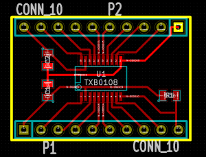
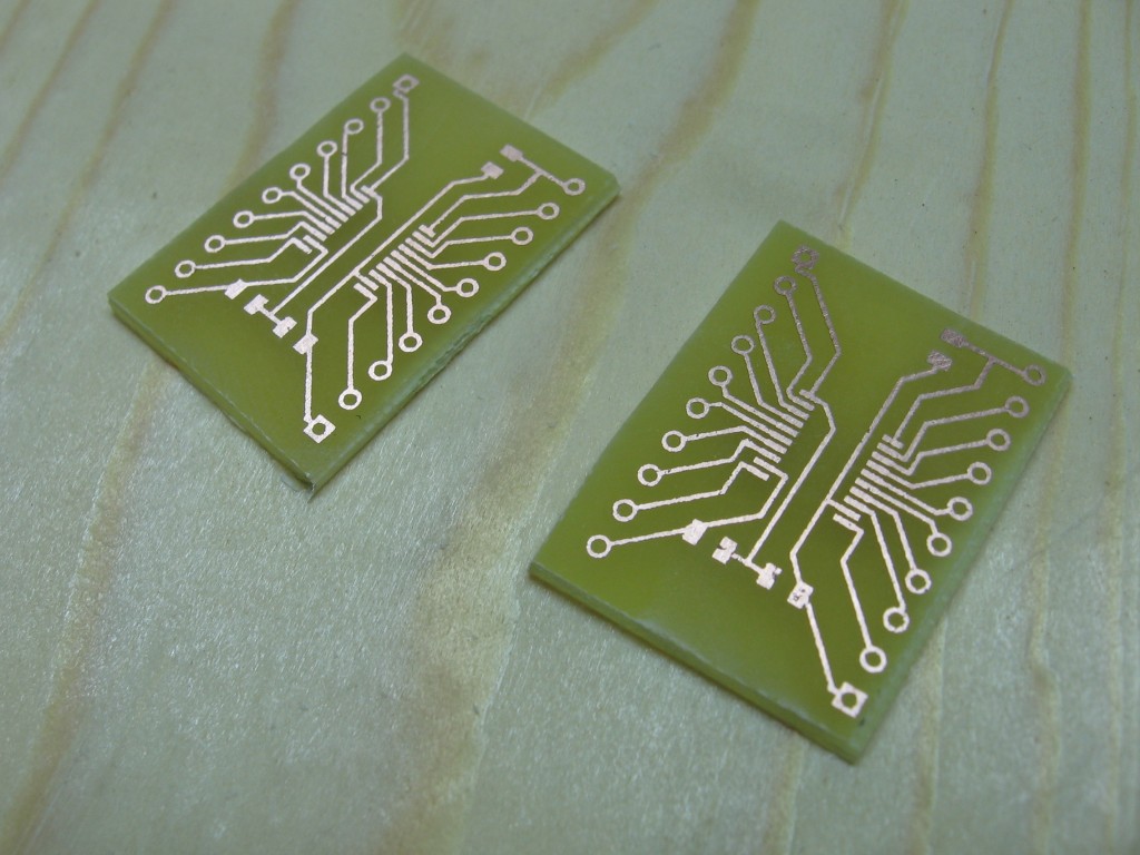
I’ve got a fair amount of equipment on hand for prototyping 5V projects. The problem is that I’m working mostly with ARM chips these days and that stuff is just sitting around gathering dust. I recently hit Mouser and started looking for what’s available when it comes to level converters. Most of them are either one-way, or have a pin that needs to be toggled to switch direction. But I found one chip that is bi-directional and sounds fantastic. TI makes the TXB0108. It’s got eight channels, one side of the chip works with 1.2V to 3.6V, the other side works with 1.65V to 5.5V. This is perfect, and will even let me prototype with some of those 1.2V EEPROM chips I bought by accident. Join me after the break to see the breakout boards I made and a quick test of the hardware.
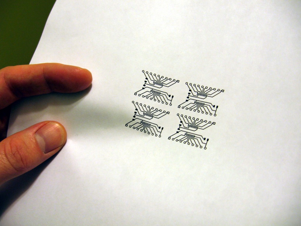 Test print of the artwork on a plain piece of paper. I forgot to mirror the design and this test helped me figure that out before etching the board.
The largest package available (read: hand solderable) is a TSSOP-20. Now I’ve soldered this pitch by hand before and it’s not all that hard. Etching the fine traces was more of a concern. I got to work in Kicad and had the resist printed out and ready to go in about 20 minutes. I always print way more than I need because hand ironing them onto the copper can be problematic. But I was lucky this time and I got two designs to transfer on the first try!
 Board being etched in Cuperic Chloride. There is boiling water in the bucket to heat the acid, and the tube from a fish tank pump to aerate it.
Etching in Cupric Chloride which I mixed up myself always takes a long time but I’ve found a better way. I fill up the tea kettle and pour the boiling water in a bucket to pre-warm the acid. I also use a fish pump to add oxygen to the acid throughout the process. This board took about 16 minutes to fully etch.
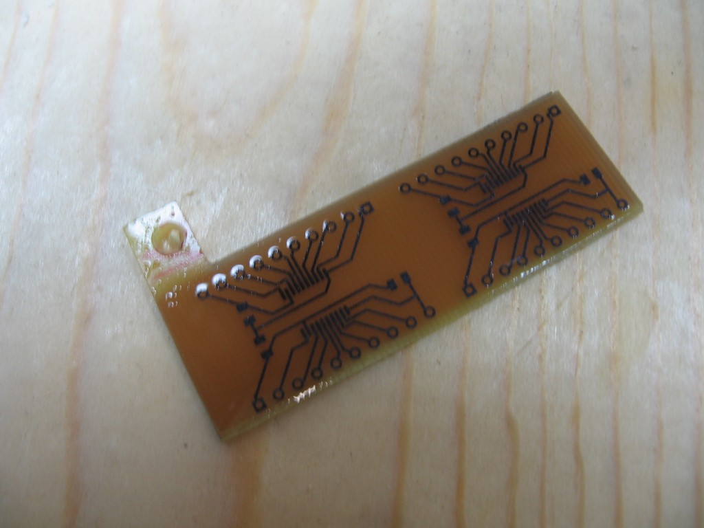 Etched boards with the resist still on the copper
You can see that I left a little tab the substrate. This is so that I can hang it from a thick piece of insulated wire (insulated to keep the acid away from the copper inside). This copper clad was double-sided stock. I make very few double-sided boards and am almost out of single-sided stock. So I just covered the back side with electrical tape so that I don’t saturate the copper chloride for no reason.
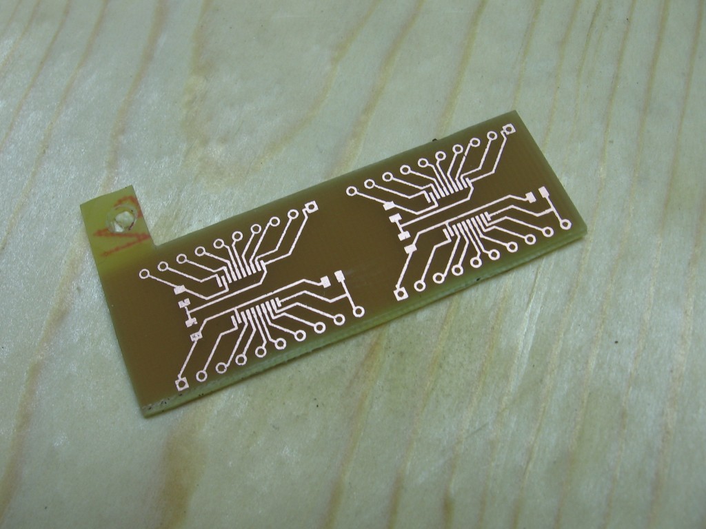 Etched boards with resist removed
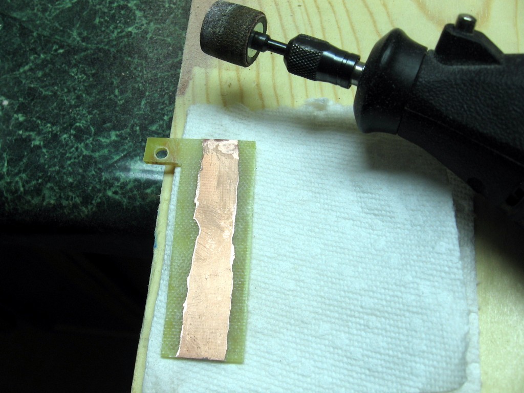 Grinding off the copper on the back side of the board (I have way too much double-sided on hand so I sometimes us it for simple boards like this one).
Now that the etching is done I simply grind off the back side of the copper clad with a sanding wheel and a Dremel tool.
I used the cutoff wheel on the Dremel too to cut the boards down to the final size. At this point I use a continuity tester to check for shorts or broken traces.
 Pin headers holes were drilled with a Dremel drill press
Drilling is done with a Dremel drill press. I find if you go slowly and have lots of light this process isn’t hard at all.
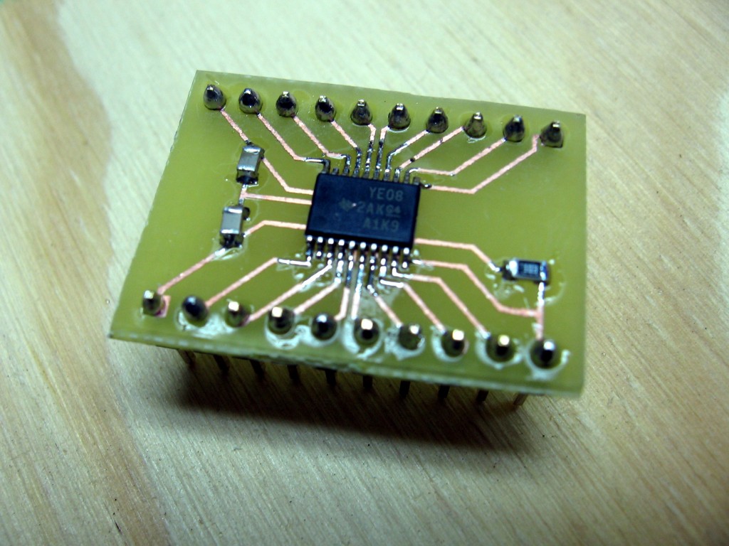 The populated level converter (TXB0108) breakout board.
Here’s the assembled board. The added components are two 0.1uf decoupling capacitors and a pull-up resistor on the OE line. This comes straight from the recommended application schematic in the datasheet. I just so happened to have the surface mount components left over from the Binary Burst clock.
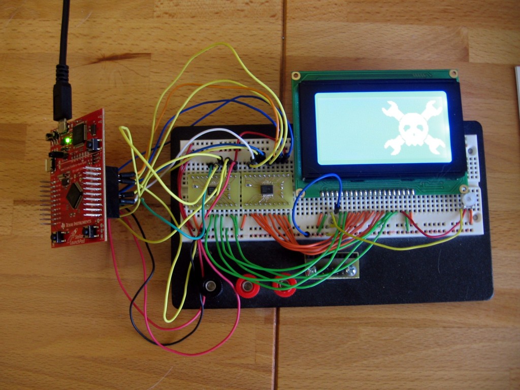 Level converters being tested with a TI Stellaris Launchpad and a 5V Graphic LCD screen (ks0108)
And here is the proof that it works. I’m driving a 5V graphic LCD using the 3.3v Stellaris Launchpad. The TXB0108 level converters have two voltage inputs. The lower voltage goes to VCCA and the higher voltage goes to VCCB. Each chip provides eight pins on either side for easy connections.
Rough road to success
I actually had quite a bit of trouble getting this display to work. I’m not sure if it’s cross talk from the wires or the capacitance of the breadboard but I had many communications failures to start with.
First off, I found out after several hours of frustration that the Stellaris Launchpad PD0 and PD1 pins are connected via a zero ohm resistor to the PB6 and PB7 pin. Needles to say, using PORTB for data and PORTD for control wasn’t working because whenever you drive the pins on one port that voltage also shows up on the other port.
There is also a rise time for the level converters. It’s rather trivial… like 40ns per volt or something, but since this ARM controller is running at 48 MHz that bug will bite you as well. Adding in appropriate delays before driving the enable pin low seems to have fixed this issue.
But I still get some garbage on the display from time to time. This can usually be fixed by straightening out the jumper wires, which is what makes me thing it is a cross talk problem. If you know what’s going on (and how to avoid it) I love to hear from you! I can’t really investigate further unless I somehow acquire an oscilloscope which can verify the quality of the signals.
The code is embarrassingly messy. But I’ve released it none-the-less. I’ve used this KS0108 library and just altered the low-level driver to work with the Stellaris chip. You’ll also find the Kicad files (and a PNG and XCF of the artwork) in the repo.
Source Code
https://github.com/szczys/stellaris-ks0108


