I’ve been investigating the calibration register of the RTC chip I used in the Binary Burst clock. While doing so, I discovered some design considerations that I didn’t manage to consider while laying out the board.
The RTC chip I’m using is from the MCP7941x family. I have the data sheet but it doesn’t show a recommended circuit. When doing some Googling about the chip I came across this application note (PDF) thanks to a post on Dangerous Prototypes.
Page 10 has an example schematic I would have like to use during my circuit design. The first thing that occurred to me is that I didn’t include a pull-up resistor on the Multi-Function Pin (MFP). This shouldn’t have mattered, since I didn’t route that pin. But now that I’m dealing with oscillator calibration I realize that I needed the pull-up resistor to make a frequency measurement.
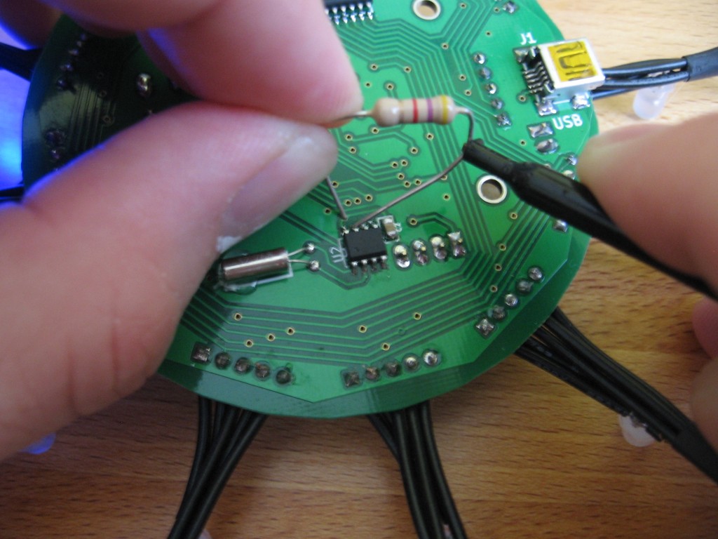
Not a huge problem, you can see how I got past it in the image at the top of this post. I’m using a resistor to connect to a via on the VCC rail with one leg, and the MFP on the other leg. This is my pull-up and I’m using my multimeter to take a frequency reading from it (don’t mind the black probe clamp… my red one is broken but this is the meter’s positive input).

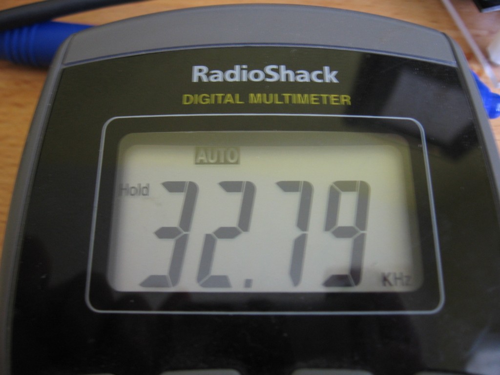
As you can see, I’m not getting the 32.768 kHz signal I was expecting. Time to use the calibration register, right? Maybe, but maybe not. There is a second test for frequency that outputs the calibration-adjusted clock signal. Nominally this is 64 Hz, and that’s what I get when I test that method. When I actually write to the calibration register with the correction calculated from the first test, I only get 59 Hz on the second test. Something doesn’t smell quite right.
So what’s the issue? I hit the application note again. Okay, I’ve included a decoupling capacitor as recommended, but two other things stick out. First, I neglected to lay out capacitors for the legs of the clock crystal. For some reason I thought this chip is designed to work without them. I also notice the protection and decoupling included on the Vbat line. Now the diode/resistor probably don’t matter as I think they’re meant for reverse polarity and over voltage protection. But the missing decoupling capacitor could be a cause for losing/gaining time when the chip is on battery backup or when the switch between Vcc and battery happens.
To tell you the truth, so far the thing runs reasonably well. I’m going look into more calibration testing and see where that gets me. The true test is to set and let it run for a month to see how much it drifts. But I will think twice before lay out for new parts without consulting the reference design, RTFM!


