I’ve been working on a way to push data into a microcontroller using a computer monitor (or smart phone) which flashes black and white. I’ve done some preliminary tests using one photoresistor read by an ATmega168 analog comparator circuit. The results have been mixed.
Analog Inputs
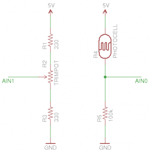
Here are the two circuits responsible for voltages being measured by the analog comparator. The circuit on the left should produce 2.5 volts on the AIN0 pin. Strictly speaking the 330 Ohm resistors (R1 and R3) are unnecessary, but I’ve included them to protect the microcontroller from unrestricted current if the trimpot is turned all the way to one side.
On the right is the circuit with the photoresistor. When it is held up to a white screen, the voltage is around 1.5 volts. A black screen produces about 3.5 volts. This is distinctly different from the 2.5V reference and easy for the analog comparator to differentiate.
The Results
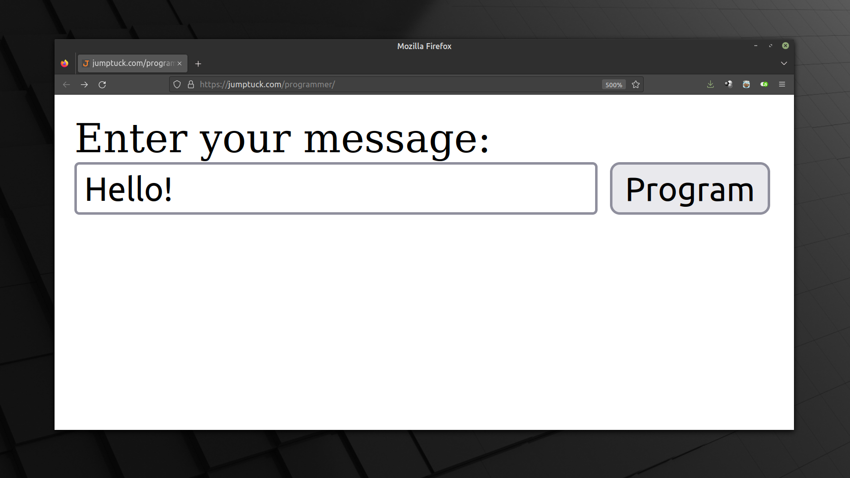
So far the results are not entirely good. I have no problem detecting edges with the comparator running in toggle mode. But when I have the microcontroller count those edges I find it’s registering multiple (sometimes dozens) of edges for each transition. I have experimented with little success to filter these out in software by checking a running timer before registering the next reading. I also tried only detecting rising edges, or switching between rising and falling detection after each interrupt. I’m not entirely certain if timing is part of the problem. I’m testing with a JavaScript application that flashes a sync signal, preamble, and data packet using Manchester encoding with 100ms bit frames. It could be that the timing for that is very unreliable, and outside of the +/- 10ms window I’m allowing for in each half-bit frame. (Give it a try if you wish)
It seems the best I can do with this method is to almost reliably count rising edges (within maybe 10%). However, I know that the ATmega168 has input capture capabilities built into Timer1 which include a hardware noise filter. I’m still studying the datasheet on how this works, but you can bank on seeing a post about that functionality soon.
This would be a lot easier to resolve if I owned an oscilloscope. I would be able to toggle a pin on the uC with each interrupt, using that output to measure the timing with the scope. Oh well… I don’t think I’ll have that tool in hand any time soon, if ever.


