Sure, there are some times when you can get away with using unregulated voltage. But if you want your project to work reliably, you need to provide a reliable power source. If you ask me, the easiest and least expensive way of doing this is to use a linear voltage regulator. You’ll need just three parts, but you might roll in a few more to add features. And the good news is that these regulators are available with many different voltage output levels.
I’m going to illustrate their use with a 7805 regulator. It puts out 5V and you can buy it at Radio Shack or order if from your favorite parts supplier. If you look hard enough you might find one to salvage in your junk bin. I’ll get started on it after the break.
The 7805 is a linear regulator that takes in DC electricity of at least 7V and outputs a constant 5V. The voltage that is shed (anything over 5V) is converted to heat. You can hook straight up to the three pins on the device without anything extra, but for reliable operation I always add two smoothing capacitors.
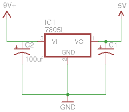
These capacitors charge up, and if the current on the input or output dips just a bit, they fill in to keep the power constant. Hence the name smoothing capacitors. For power supplies these are usually electrolytic capacitors because of the traits they supply. The most basic 7805 circuit looks like this:
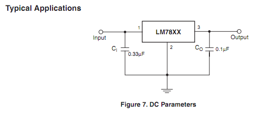
You can see there’s a bigger capacitor on the input than on the output. How did I come up with this? The parts manufacturer usually lists a recommended use schematic in the datasheet for the regulator. For instance, Fairchild’s datasheet (PDF) shows this on page 22:
Hardware build
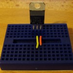 Breadboarding this circuit is very simple. First I position the linear regular. The middle pin is ground. In this picture the pin on the left is the input, the pin on the right the output. I’ve added a yellow wire for the output ground, and an orange wire for the output voltage.
Next I squeeze in the two electrolytic capacitors. These are polarized capacitors with a stripe on the negative side. Make sure the strip points to ground!
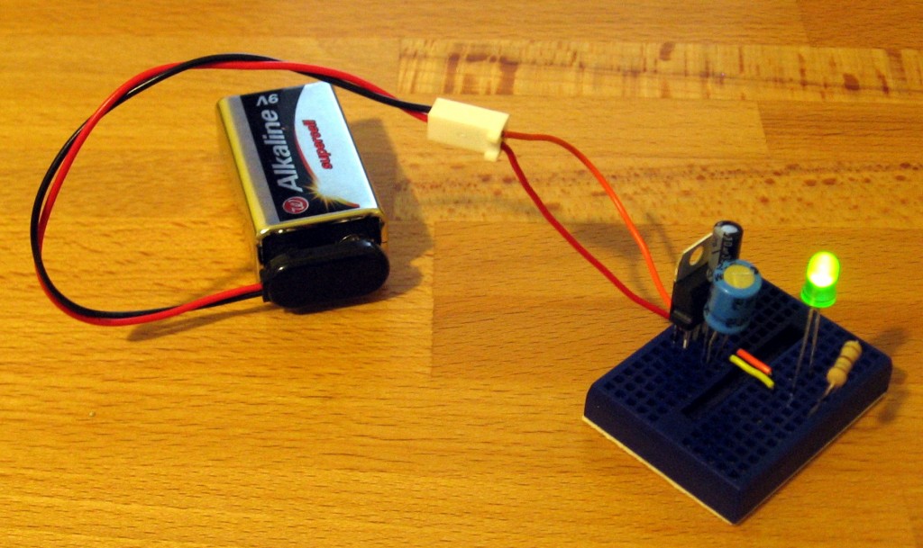
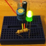 Here is our simple voltage regulator circuit, being fed by a 9 volt battery, and powering an LED. It works great, but you need to unplug the battery to shut it off. I can do better than that.
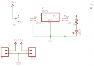
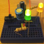 This version has an on/off switch, and a power LED. These are simple to add. The switch connects the incoming battery connection to the 7805. The power LED (and its resistor) just goes between ground and the output pin of the regulator. If you need help figuring out how to add the status LED, check out this post.
My enhanced voltage regulator schematic
Turn it into a breadboard power supply
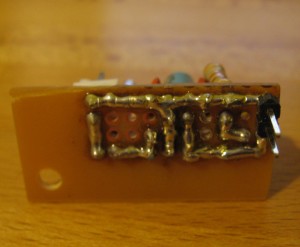
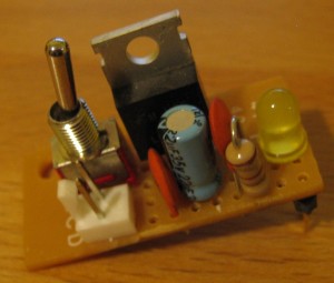
Why build this on a breadboard each time when a bit of soldering makes it plug and play? Here’s the first breadboard power supply I ever made. It was assembled on the corner of a breadboard and has one pin header for the incoming power (9V battery most of the time) and two pins on the bottom to plug into the power rails of my breadboard.


