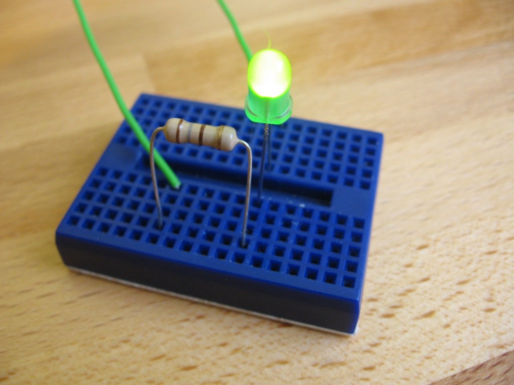
One of the first thing’s you’re going to want to do when getting into hobby electronics is to light up some LEDs. Take the time to read through this guide and you’ll have a basic understanding of how they work and how to use them.
About the hardware:
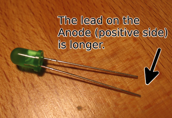
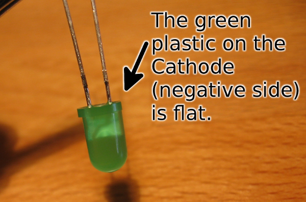
LED stands for Light Emitting Diode. The Light Emitting part is easy enough to understand. The Diode parts tells you something important: electricity can only flow in one direction through it. This means there is a positive and negative side to the diode and it must be hooked up correctly to work. Here’s how to tell which is which:
- The positive lead (the wire coming out of the body) will be longer than the negative one
- The plastic case on the negative side of the LED will have a flat spot (some of it is missing = negative).
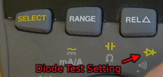
UPDATE: It is good practice to check polarity using the diode setting on a multimeter. The multimeter should show a voltage (this is the Forward Voltage I’ll talk about in just a minute) if you have to meter’s probes connected properly. Otherwise it will show infinite resistance if it is hooked up backwards. This is by far the most reliable way to tell which side of the LED is positive and which is negative. On my meter, the diode test is a symbol in yellow. I get there by turning the knob to that icon, then pressing the Select button:
Thanks Reddit for suggesting I add this update.
How to hook it up:
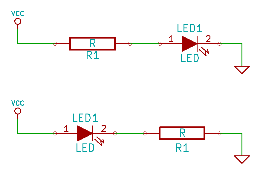 The resistor can be on either side of the LED and it will have the same effect.
In almost every case you’ll need an additional part in order to connect an LED correctly. LEDs require a specific current to function and if they get too much they’ll burn out. Because of this you need to use a resistor to limit the current flow. This resistor can be on either side of the LED, as long as it’s there it makes no difference.
Notice the schematic symbol for an LED seen above. The negative side (cathode) has a line through it. I think of this as cutting away that side, just like the flat side on the plastic LED case.
How to establish which resistor you need:
You can calculate the value of the resistor that you need, but this isn’t necessarily the end of the story (as I’ll discuss in just a minute). To do this we’ll need to use Ohm’s Law. It has three parts to it: Voltage, Current, and Resistance. As long as you know two of them you can always calculate the third.
Look at the datasheet for the LEDs you are using (for instance, this datasheet (PDF) for an LED sold by SparkFun). You need to find information about voltage and current in order to calculate your resistance:
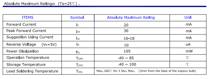
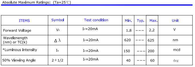 The two tables above have the values we’re looking for. The top table has “suggested using current” of 16-18 mA. The table below that has “forward voltage” of 1.8-2.2 Volts.
Forward voltage is sometimes called voltage drop. It’s the difference between the voltage going into the LED and the voltage coming out. Now that we’ve found this number we can subtract it from our supply voltage, which we’ll say is 5V
5V supply - 2.0V forward voltage = 3V
We also need to convert the current rating, which is given in milliamps to Amps. The International System of Units tells us that we can move the decimal point three places to the left to make this conversion:
18 mA / 1000 = 0.018 Amps
Finally, we can plug these into Ohm’s law to calculate our resistance:
R = V/I
R = 3V/0.18A
R = 167 Ohms
We need a 167 Ohm resistor, which is not a standard value. But if we look at the E24 series we see that this is not an option (resistors come in values that are multiples of 10 in this series). No problem, just choose the next larger value of 180 Ohms. If you do the math you’ll find that a 180 Ohm resistor should allow 16.6 mA of current which is still within the recommended range from the datasheet.
Calculations are different from real life
The datasheet has ranges for forward voltage and operating current. That’s because parts have built-in tolerances that will be a bit different from one to the next. It’s a good idea to actually measure the current flow with the calculated resistor value and decide if an adjustment should be made.
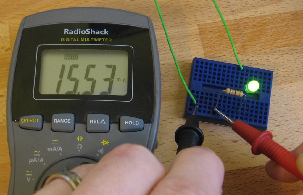
Taking a current measurement is quite easy. I use a Digital Multimeter and put it in series with the diode and resistor. Here you can see that I’m using a 180 Ohm resistor, with a 5V power source, and measuring 15.53 mA. That’s different from my calculations, but it’s not more than the absolute maximum rating for the LED.
This is close enough to the suggested operating current of 16-18 mA for my purposes. But you could get a slightly brighter LED if you tried using the next smaller resistor value of 150 Ohm. In my experience, the difference that 1 or 2 mA makes in brightness cannot be picked up by the human eye so swapping parts is probably not worth the effort.
Driving LEDs in series
The math is just as easy if you want to drive LEDs in series. Just add up their forward voltages and subtract that number from the input voltage. The rest of the math is the same; you still want to aim for 16-18 mA total and you can use just one resistor.
Conclusion
Working with LEDs is simple, and as long as you never use more current than the maximum rating you won’t risk burning them out. A Digital Multimeter (which I used for measuring current through my LED) is a must for electronic work. Pick up one that’s nice, but doesn’t break the bank (I think mine was around $40). Don’t get me wrong, I’d love to have a Fluke 87 but since I’m not doing professional work I would be prefectly happy with the Extech EX330 which got a pretty good review from Dave Jones.
You can get by without any other bench equipment for quite some time as long as you have one of these.


